208 www.xilinx.com Virtex-5 RocketIO GTP Transceiver User Guide
UG196 (v1.3) May 25, 2007
Chapter 10: GTP-to-Board Interface
R
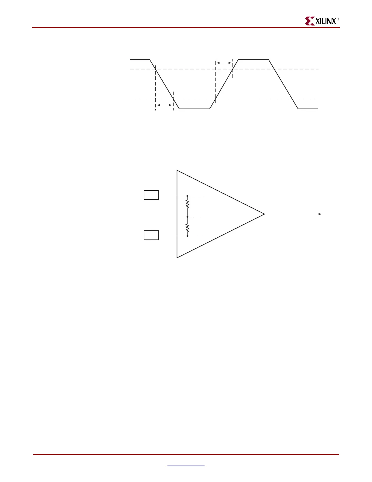
Figure 10-8 shows the rise and fall time convention of the reference clock.
Figure 10-9 illustrates the internal details of the IBUFDS. The dedicated differential
reference clock input pair MGTREFCLKP/MGTREFCLKN is internally terminated with
100Ω differential impedance. The common mode voltage of this differential reference clock
input pair is 2/3 of MGTAVCCPLL.
If the common mode voltage of the driving clock source is different from the common
mode voltage of the differential reference clock input pair, then AC coupling capacitors are
mandatory to prevent device degradation and/or other damage.
Figure 10-8: Rise and Fall Time
Figure 10-9: IBUFDS Details
UG196_c10_08_100506
80%
20%
T
FCLK
T
RCLK
UG196_c10_09_042807
to GTP
Dedicated
Clock
Routing
REFCLK
MGTREFCLKP
MGTREFCLKN
MGTAVCCPLL
2
3
50Ω
(1)
50Ω
(1)
Notes:
1. Nominal values. Refer to the Virtex-5 Data Sheet for exact specifications.
 Loading...
