Table 12: GTM Transceiver Reset Modes Ports
Port Direction Clock Domain Description
CH[0/1]_RXRESETMODE[1:0] In Async Reset mode port for RX.
2'b00: Sequential mode
(recommended).
2'b01: Reserved.
2'b10: Reserved.
2'b11: Single mode.
CH[0/1]_TXRESETMODE[1:0]
In Async Reset mode port for TX.
2'b00: Sequential mode
(recommended).
2'b01: Reserved.
2'b10: Reserved.
2'b11: Single mode.
LCPLL Reset
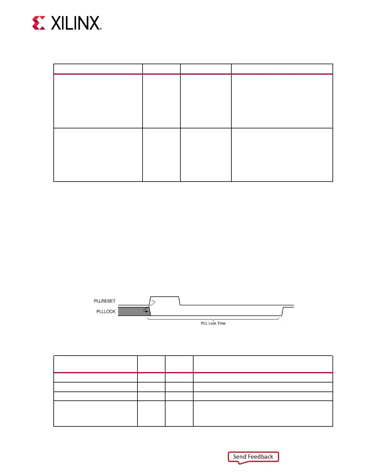
The LCPLL must be reset before it can be used. Each GTM transceiver dual has dedicated reset
ports for its LCPLL. As shown in the gure, PLLRESET is an input that resets LCPLL. PLLLOCK is
an output that indicates the reset process is done. The guideline for this asynchronous PLLRESET
pulse width is one period of the reference clock. Aer a PLLRESET pulse, the internal reset
controller generates an internal LCPLL reset followed by an internal SDM reset. The me
required for LCPLL to lock is aected by a few factors, such as bandwidth seng and clock
frequency.
Figure 12: LCPLL Reset Timing Diagram
Table 13: LCPLL Reset Ports
Port Dir
Clock
Domain
Description
PLLRESET In Async Active-High signal that resets the LCPLL.
PLLRESETMASK[1:0] In Async Reserved. Tied to 2’b11.
PLLRESETBYPASSMODE In Async Reserved. Tied Low.
PLLLOCK Out Async Active-High LCPLL frequency lock signal indicates that the
LCPLL frequency is within a predetermined tolerance. The
GTM transceiver and its clock outputs are not reliable until
this condition is met.
Chapter 2: Shared Features
UG581 (v1.0) January 4, 2019 www.xilinx.com
Virtex UltraScale+ GTM Transceivers 26
 Loading...
