ZCU111 Board User Guide 16
UG1271 (v1.1) August 6, 2018 www.xilinx.com
Chapter 2: Board Setup and Configuration
Default Jumper and Switch Settings
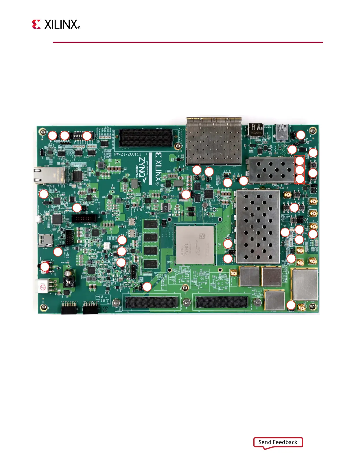
Figure 2-2 shows the ZCU111 board jumper header and switch locations. Each numbered
component shown in the figure is keyed to Tab le 2- 2 (for default jumper settings) or
Tab l e 2- 3 (for default switch settings). Both tables reference the respective schematic page
numbers.
X-Ref Target - Figure 2-2
Figure 2-2: Board Jumper Header and Switch Locations
1
2
4
3
8
9
10
11
12
15
14
13
16
18
17
19
20
27 23
25
26
29
32
28
24
21
22
31
7
6
5
30
X20479-062118

 Loading...


