ZCU111 Board User Guide 65
UG1271 (v1.1) August 6, 2018 www.xilinx.com
Chapter 3: Board Component Descriptions
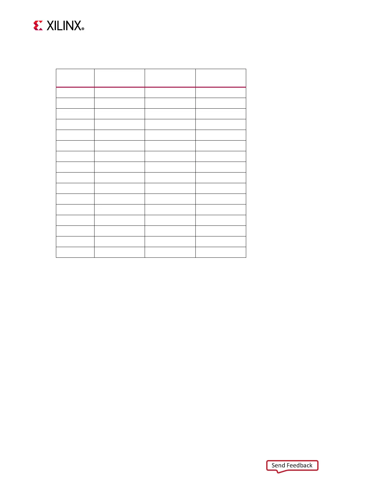
Tab l e 3- 2 3 lists the connections between the XCZU28DR RFSoC and the PMOD
For more information on the PMOD interface, see the Digilent website [Ref 27].
User I/O
[Figure 2-1, callouts 22-25]
The ZCU111 board provides these user and general purpose I/O capabilities:
• Eight user LEDs (callout 22)
°
GPIO_LED[7-0]: DS11, DS12, DS13, DS14, DS15, DS16, DS17, DS18
• 8-position user DIP Switch (callout 23)
°
GPIO_DIP_SW[7:0]: SW14
• Five user pushbuttons and CPU reset switch (callouts 24 and 25)
°
GPIO_SW_[NWCES]: SW9, SW10, SW11, SW12, SW13
°
CPU_RESET: SW15
Table 3-23: PMOD Connections to XCZU28DR
XCZU28DR
(U1) Pin
Net Name
(1)
I/O Standard PMOD Pin
C17 PMOD0_0 LVCMOS12 J48.1
M18 PMOD0_1 LVCMOS12 J48.3
H16 PMOD0_2 LVCMOS12 J48.5
H17 PMOD0_3 LVCMOS12 J48.7
J16 PMOD0_4 LVCMOS12 J48.2
K16 PMOD0_5 LVCMOS12 J48.4
H15 PMOD0_6 LVCMOS12 J48.6
J15 PMOD0_7 LVCMOS12 J48.8
L14 PMOD1_0 LVCMOS12 J49.1
L15 PMOD1_1 LVCMOS12 J49.3
M13 PMOD1_2 LVCMOS12 J49.5
N13 PMOD1_3 LVCMOS12 J49.7
M15 PMOD1_4 LVCMOS12 J49.2
N15 PMOD1_5 LVCMOS12 J49.4
M14 PMOD1_6 LVCMOS12 J49.6
N14 PMOD1_7 LVCMOS12 J49.8
Notes:
1. Level-shifted net names at XCZU28DR have _LS appended.

 Loading...


