ZCU111 Board User Guide 35
UG1271 (v1.1) August 6, 2018 www.xilinx.com
Chapter 3: Board Component Descriptions
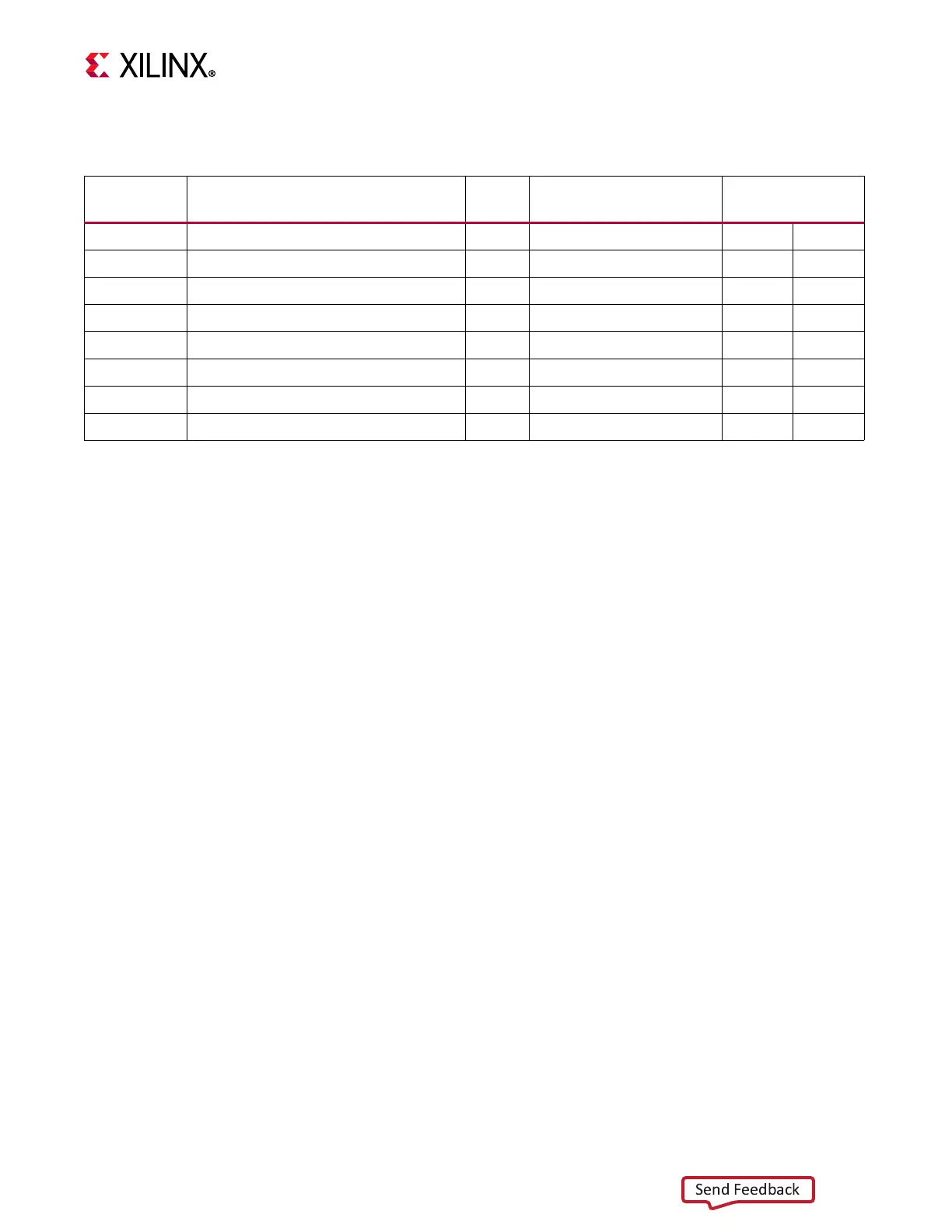
The FT4232HL U34 UART connections are listed in Tabl e 3-9 .
For more information on the FT4232HL, see the Future Technology Devices International Ltd
website [Ref 26].
UART1 (MIO 20-21)
The PS-side UART1 is not connected.
GPIO (MIO 22-23)
The PS-side pushbutton SW19 is connected to MIO22 (pin U1.Y28). The PS-side LED DS50,
which is physically placed adjacent to the pushbutton, is connected to MIO23 (pin U1.U29).
CAN1 (MIO 24-25)
The PS-side CAN bus TX and RX MIO pins are not connected.
PMU GPI (MIO 26)
The PS-side MIO 26 is reserved as an input to the PMU for indicating a warm boot. PS bank
501 MIO26 (U1.G25) is connected to the I2C0 U22 TCA6416A bus expander (port P02 U22.6)
through a 0Ω series resistor R92. See the Zynq UltraScale+ Device Technical Reference
Manual (UG1085) [Ref 3] for more details about the PMU interface.
DPAUX (MIO 27-30)
[Figure 2-1, callout 29]
The Zynq UltraScale+ RFSoC provides a VESA DisplayPort 1.2 source-only controller that
supports up to two lanes of main link data at rates of 1.62 Gb/s, 2.70 Gb/s, or 5.40 Gb/s. The
Table 3-9: FT4232HL UART Connections
FT4232HL
U34 Pin
Schematic Net Name
Level
Shifter
Level-Shifted Net Name
Target UART
Ref Des., Pin
26 LS_UART0_TXD_OUT U21 UART0_TXD_MIO18_RXD U1 Y27
27 LS_UART0_RXD_IN U21 UART0_RXD_MIO19_TXD U1 W28
38 LS_UART2_TXD_OUT U21 UART2_TXD_FPGA_RXD U1 AT15
39 LS_UART0_RXD_IN U21 UART2_RXD_FPGA_TXD U1 AU15
40 LS_UART2_RTS_B U21 UART2_RTS_B U1 AU14
41 LS_UART2_CTS_B U21 UART2_CTS_B U1 AT14
48 UART3_TXD_O_MSP430_UCA0_RXD NA NA U42 26
52 UART3_RXD_I_MSP430_UCA0_TXD NA NA U42 25

 Loading...


