ZCU111 Board User Guide 19
UG1271 (v1.1) August 6, 2018 www.xilinx.com
Chapter 2: Board Setup and Configuration
Switches
7-8:
22 J110 U92 12.8MHz TXCO power On 67
On: U92 is on
Off: U92 is off
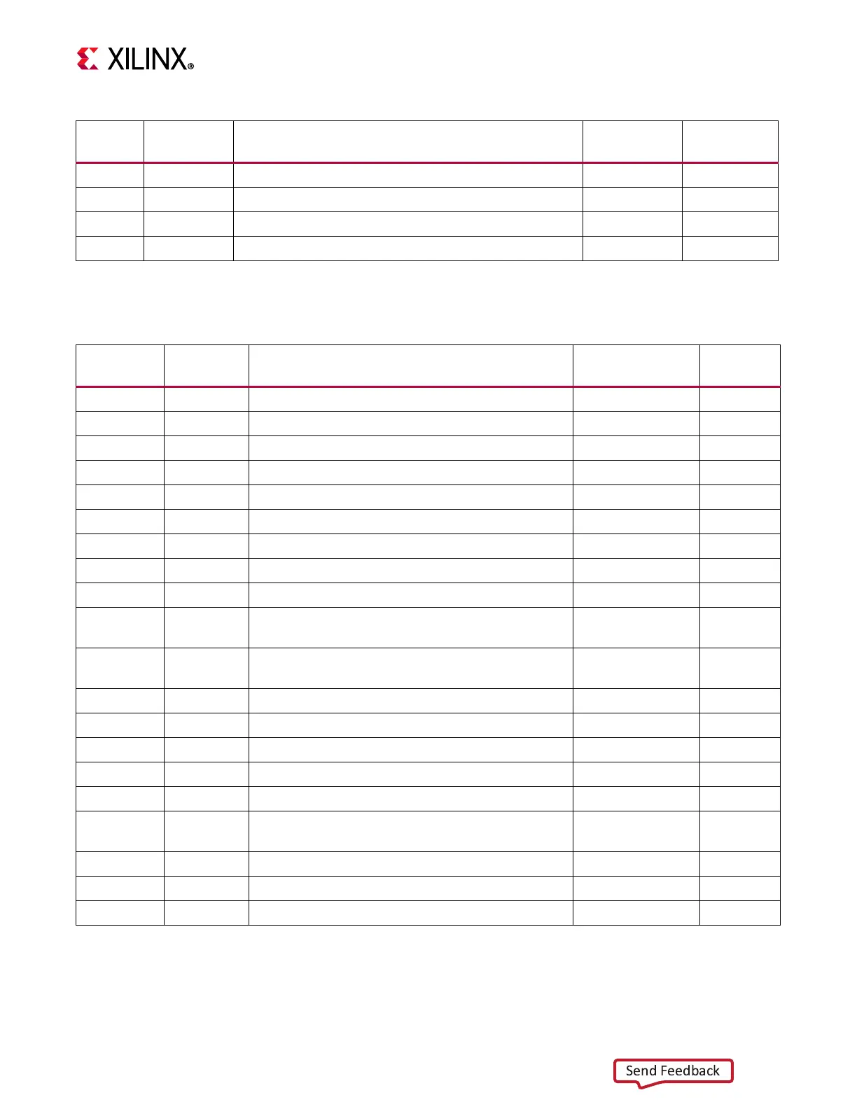
Table 2-2: Default Jumper Settings (Cont’d)
Callout
Number
Ref Des Function Default
Schematic
Page
Table 2-3: Default Switch Settings
Callout
Number
Ref Des Function Default
Schematic
Page
23 SW6 RFSoC U1 Mode 4-Pole DIP Switch 0010 12
Switch OFF = 1 = High; ON = 0 = Low
Mode = SW6[4:1] = Mode[3:0]
JTAG = ON,ON,ON,ON = 0000
QSPI32 = ON,ON,OFF,ON = 0010
SD = OFF,OFF,OFF,ON = 1110
24 SW2 PS_PROG_B pushbutton
(1)
12
25 SW3 PS_POR_B pushbutton
(1)
12
SW4 PS_SRST_B pushbutton
(1)
12
26 SW8
MSP430 U42 5-Pole GPIO DIP switch
Switch Off = 1 = High; On = 0 = Low
11111 32
27 SW8
RST_B pushbutton for MSP430 U42/MSP430
EMUL. cable J92
(1)
32
28 SW9 GPIO pushbutton (geographic) GPIO_SW_N
(1)
41
SW10 GPIO pushbutton (geographic) GPIO_SW_W
(1)
41
SW11 GPIO pushbutton (geographic) GPIO_SW_C
(1)
41
SW12 GPIO pushbutton (geographic) GPIO_SW_E
(1)
41
SW13 GPIO pushbutton (geographic) GPIO_SW_S
(1)
41
29 SW14
GPIO 8-Pole DIP switch
Switch Off = 0 = Low; On = 1 = High
00000000 41
30 SW15 CPU_RESET pushbutton
(1)
41
31 SW16 Main power slide switch off 46
32 SW19 PS MIO22_BUTTON pushbutton
(1)
11
Notes:
1. Pushbutton switch default = open (not pressed).

 Loading...


