ZCU111 Board User Guide 39
UG1271 (v1.1) August 6, 2018 www.xilinx.com
Chapter 3: Board Component Descriptions
The connections between the SD NXP IP4856CX25 (U107) level-shifter and the XCZU28DR
RFSoC PS bank 501 are referenced in Appendix B, Xilinx Design Constraints.
USB0 (MIO 52-63)
The USB interface on the PS-side serves multiple roles as a host or device controller. The
USB 3.0 interface is supported by the RFSoC GTR interface while the USB 2.0 capabilities of
the SMSC USB3320C controller are shared on a common USB 3.0 micro USB type A
connector (J96).
USB 3.0 Transceiver and USB 2.0 ULPI PHY
[Figure 2-1, callout 5]
The ZCU111 board uses a Standard Microsystems Corporation USB3320 USB 2.0 ULPI
transceiver at U12 to support a USB connection to the host computer (see Figure 3-8). A
USB cable is supplied in the ZCU111 evaluation kit (standard-A connector to host computer,
USB 3.0 A connector to ZCU111 board connector J96). The USB3320 is a high-speed USB 2.0
PHY supporting the UTMI+ low pin interface (ULPI) interface standard. The ULPI standard
defines the interface between the USB controller IP and the PHY device, which drives the
physical USB bus. Using the ULPI standard reduces the interface pin count between the USB
controller IP and the PHY device.
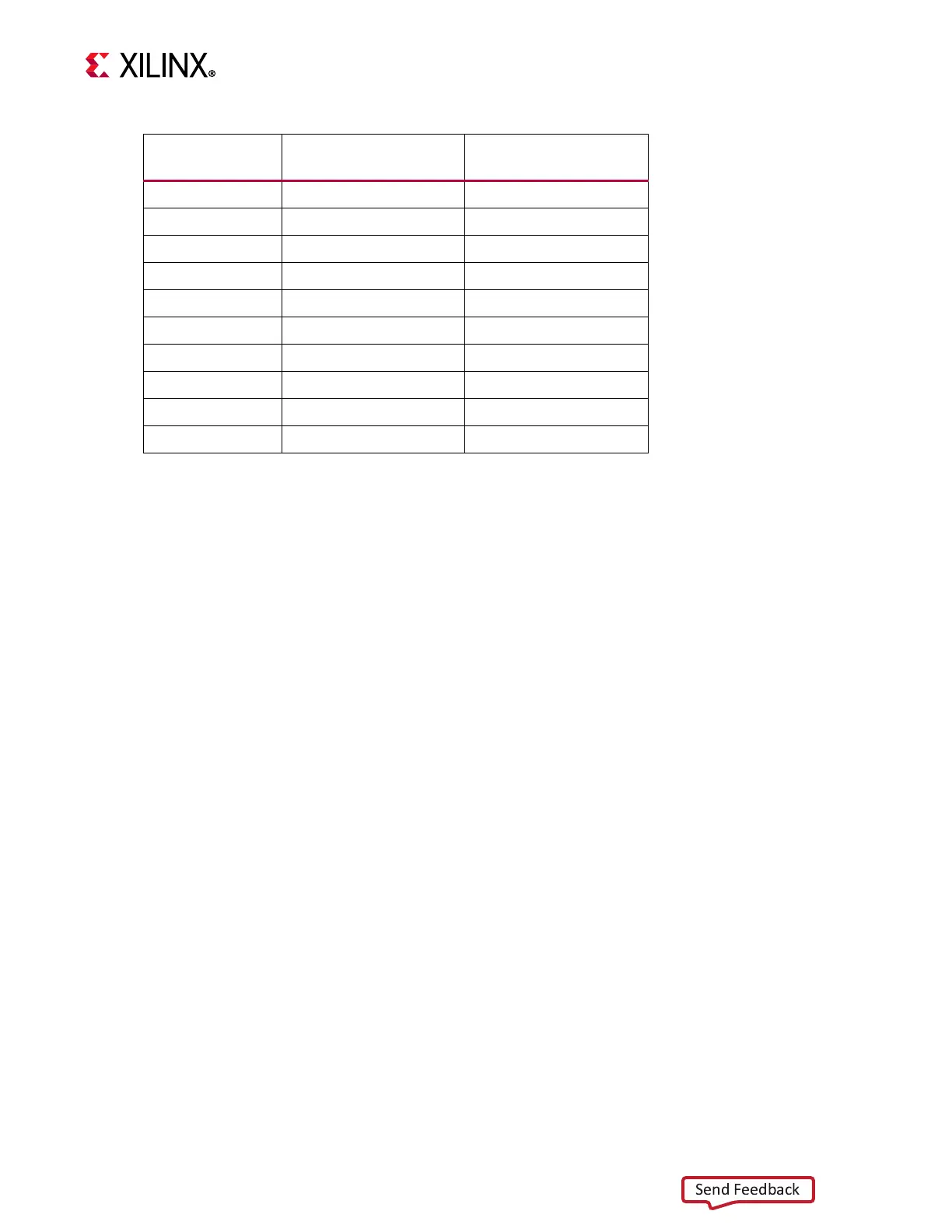
16 E1 DATA1_H
17 E3 DIR_1_3
18 A1 DATA2_H
19 E5 DATA1_SD
20 D5 DATA0_SD
21 C5 CLK_SD
22 D4 CMD_SD
23 B5 DATA3_SD
24 A5 DATA2_SD
25 C2 ENABLE
Table 3-12: IP4856CX25 U107 Adapter Pin-Out (Cont’d)
Aires Adapter Pin
Number
IP4856CX25 U107 Pin
Number
IP4856CX25 U107 Pin
Name

 Loading...


