3-2. Control terminal explanation and wiring
The numbers of the following connectors are in the order when looking at the solder patch.
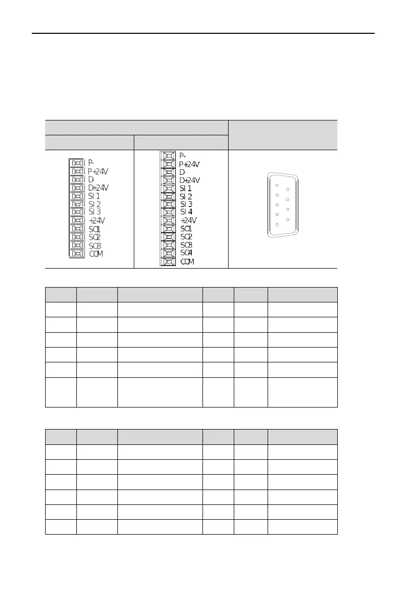
3-2-1.DS5E/L series control terminals
CN0
CN1
Below 1.5KW 1.5KW and up
CN0 terminal explanation (below 1.5KW, 3 inputs, 3 outputs)
No. Name Explanation No. Name Explanation
1 P- Pulse input PUL- 7 SI3 Input terminal 3
2 P+24V Open collector input 8 +24V Input +24V
3 D- Direction input DIR- 9 SO1 Output terminal 1
4 D+24V Open collector input 10 SO2 Output terminal 2
5 SI1 Input terminal 1 11 SO3 Output terminal 3
6 SI2 Input terminal 2 12 COM
Output terminal
ground
CN0 terminal description (above 1.5KW, 4 inputs, 4 outputs)
No. Name Explanation No. Name Explanation
1 P- Pulse input PUL- 8 SI4 Input terminal 4
2 P+24V Open collector input 9 +24V Input +24V
3 D- Direction input DIR- 10 SO1 Output terminal 1
4 D+24V Open collector input 11 SO2 Output terminal 2
5 SI1 Input terminal 1 12 SO3 Output terminal 3
6 SI2 Input terminal 2 13 SO4 Output terminal 4
37
 Loading...


