3-4.Power loss brake(BK)
3-4-1.Wiring example
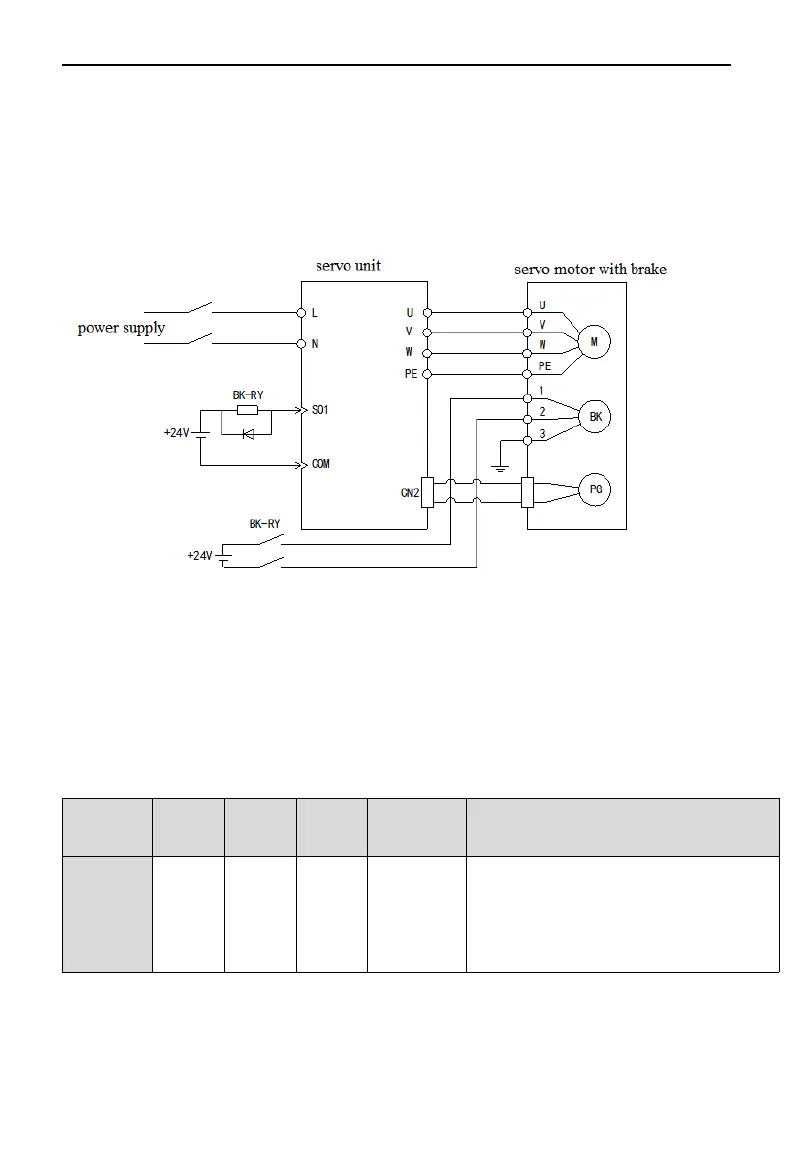
The sequential output signal "/ BK" and "brake power supply" of the servo unit constitute the on / off circuit of
the brake. Typical connection examples are shown below.
Note:
(1) The voltage of the brake is 24V.
(2) In the above figure, BK signal is output by SO1, and parameter P5-44 should be set to n.0001. If it is output
from SO2, P5-44 should be set to n.0002.
(3) If the holding brake current is more than 50mA, please transfer it through relay to prevent burning the
terminal due to excessive current.
3-4-2.Brake signal
Parameter Signal
name
Type Default
setting
Meaning Modification
P5-44 /BK Output n.0000 Unassigned
output
signal
terminal
The parameter range 0000-0014 is assigned to
the output interface through parameter P5-44.
When set to 0001, it indicates that a signal is
output from SO1 terminal.
3-4-3.Switch time between BK and SON signal
Due to the action delay time of the brake, the machinery moves slightly under the action of gravity, etc. P5-07
42
 Loading...


