7 SI3 Input terminal 3 14 COM
Output terminal
ground
CN1 terminal explanation(5L series CN1terminals have no definition)
No. Name Explanation No. Name Explanation
1 GND GND-485 2 A1 RS485+
3 B1 RS485- 4 A2 RS485+
5 B2 RS485- 6 GND GND-485
7 NC Reserved 8 NC Reserved
9 NC Reserved 9 NC Reserved
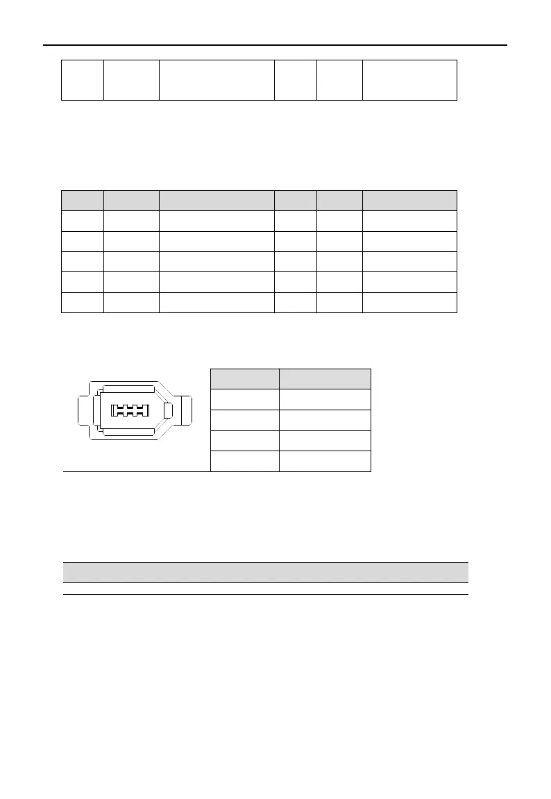
CN2 terminal explanation
The terminals of the CN2 connector are arranged as follows (faced solder plates):
No. Definition
1 5V
2 GND
5 485-A
6 485-B
3-2-2.DS5E/L series control terminal wiring
Pulse input signal
The interface circuit of open collector / differential signal pulse input, and the wiring diagram is as follows:
Open collector(24V)
PLC, CNC and SCM servo driver
38
 Loading...


