Gain switching condition setting Related parameter
P1-
14.1
condition Diagram
P1-15
Wait
time
P1-16
Grade
threshol
d
P1-17
thresho
ld
Hystere
sis loop
When the absolute value of the actual speed exceeds (level + hysteresis) [RPM] at
the last first gain, switch to the second gain;
At the last second gain, the absolute value of the inter speed is less than (level-
hysteresis) [RPM], and then wait until P1-15 remain in this state, return to the first
gain.
A
Position
command+
actual
speed
Valid
Valid(r
pm)
Valid(
rpm)
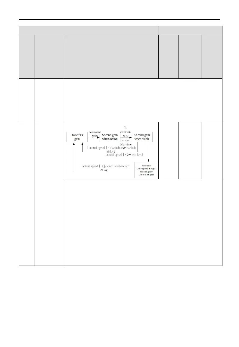
Valid only in position mode (other modes are fixed as the first gain):
In the last first gain, if the position command is not 0, switch to the second gain;
At the last second gain, the state in which the position command is 0 maintains the
second gain within the waiting time P1-15;
When the position command is 0 and the waiting time P1-15 arrives, if the absolute
value of the actual speed is less than (level) [RPM], the speed integral time constant
is fixed at the second speed loop integral time constant (P1-07), and the others
return to the first gain; If the absolute value of the actual speed is less than (level-
hysteresis) [RPM], the speed integral also returns to the integral time constant of the
first speed loop (P1-02).
5-7. Solution of vibration problem
There are two possible reasons for resonance during gain adjustment: one is mechanical resonance and the
other is too high servo gain. How to judge the two reasons?
After estimating the inertia, the driver uses the default rigidity level. If the servo runs stably but there is
high-frequency noise, reduce the rigidity level. If there is still high-frequency noise from 15 to 10, it is
70
 Loading...


