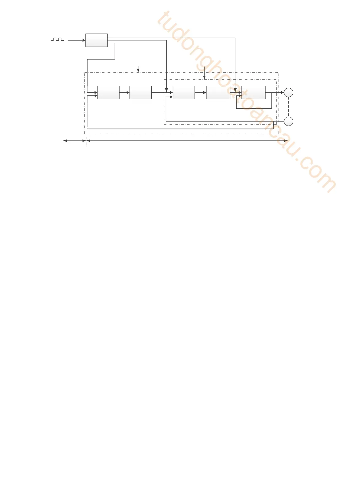
Position control loop diagram (turn on the model loop)
Servo unit consists of three feedback loops (current loop, speed loop and position loop) from inside to
outside. The more inner loop, the more responsive it is. Failure to comply with this principle will result
in poor response or vibration. Among them, the current loop parameters are fixed values to ensure
adequate responsiveness, and users do not need to adjust.
Please use manual adjustment in the following occasions:
• When the expected effect can not be achieved by fast adjusting the gain
• When the expected effect is not achieved by automatically adjusting the gain
6.5.2 Adjustment steps
In position mode, if the soft mode (P2-02.0=1) is selected by auto-tuning, the function of model loop
will be turned off; in speed mode, the gain of position loop will be invalid.
Increasing response time
1. Reducing the filter time constant of torque instruction (P2-35)
2. Increasing Speed Loop Gain (P1-00)
3. Reducing Integral Time Parameter of Speed Loop (P1-01)
4. Increasing the gain of position loop (P1-02)
5. Improving Model Loop Gain (P2-49)
Reduce response, prevent vibration and overshoot
1. Reducing the Speed Loop Gain (P1-00)
2. Increasing Integral Time Constant of Speed Loop (P1-01)
3. Reducing the gain of position loop (P1-02)
4. Increase the filter time constant of the torque instruction (P2-35)
5. Reducing Model Loop Gain (P2-49)
 Loading...

