Page 110 FTDX5000 OPERATING MANUAL
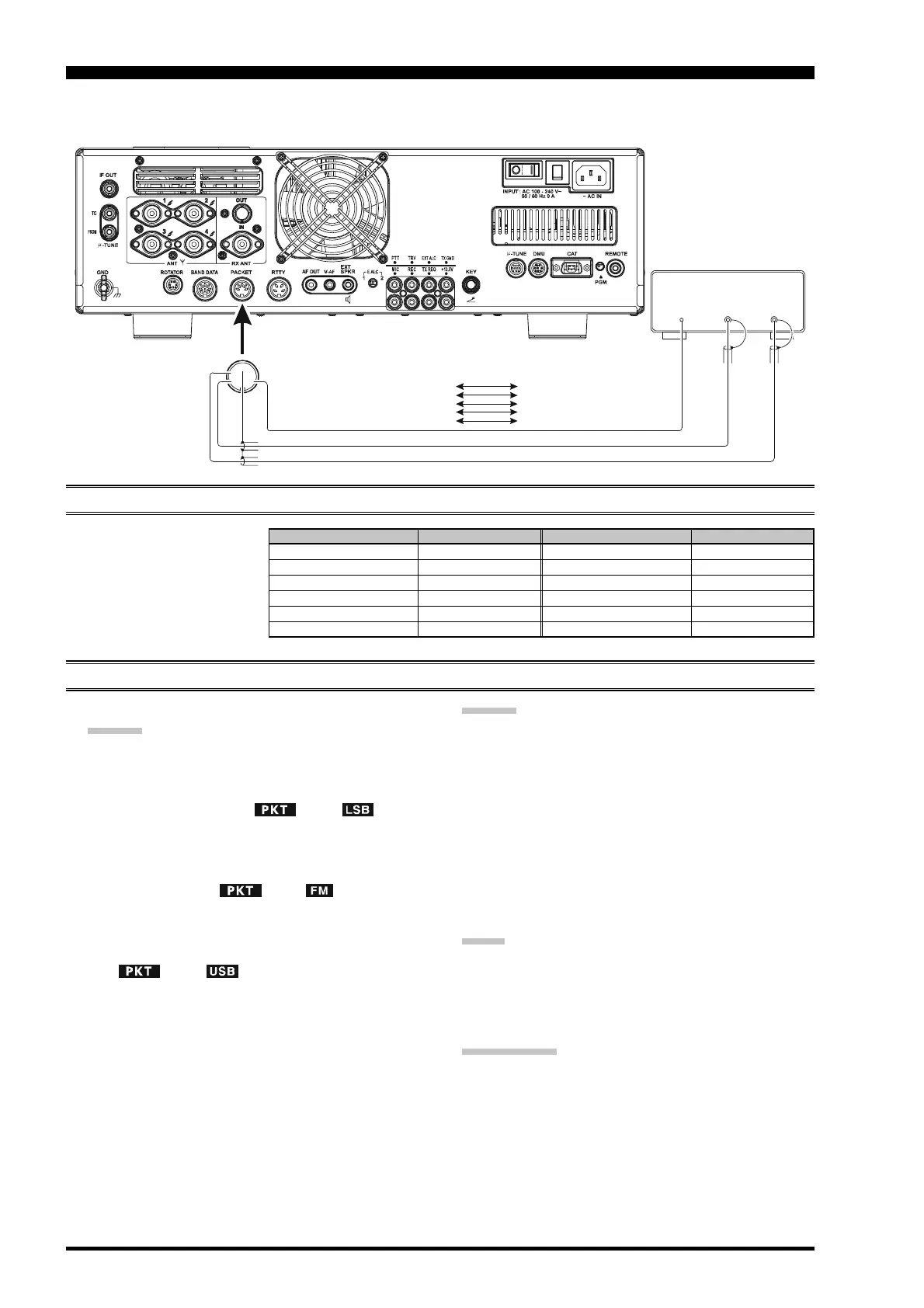
Packet operation is easily accomplished on the FTDX5000 by connecting your TNC (Terminal Node Controller) to the
transceiver, as in the illustration. “Packet” operation also applies to SSB-based AFSK data modes, such as PSK31, etc.
PACKET OPERATION
PACKET SETUP
(
INCLUDING SUBCARRIER FREQUENCY
)
Before operation can com-
mence, some basic setup proce-
dures must be performed, using
the Menu, to configure your ra-
dio for the desired data mode.
BASIC SETUP
1. Press the
[
PKT
]
button.
ADVICE:
For HF operation, SSB-based data operation is gen-
erally used. One brief press of the
[
PKT
]
button
will engage packet operation in the “LSB” mode
(by default). Both the “ ” and “ ” icons
will appear in the display.
To operate FM-based 1200-baud packet on the 29/
50 MHz bands, press the
[
PKT
]
button repeatedly
to illuminate the “ ” and “ ” icons, to en-
gage the “PKT-FM” mode.
To engaged Packet operation in the “USB” mode,
repeat pressing the
[
PKT
]
button until both the
“ ” and “ ” icons are appear.
2. When the “transmit” command is received from the
TNC, the FTDX5000 transmitter will automatically be
engaged. Likewise, the command to return to receive
will cause the radio to revert to the receive mode.
ADVICE:
If you need to adjust the output level from the “DATA
OUT” pin of the PACKET jack (pin 4) on the radio,
use Menu item “072 DATA OUT LVL”. For the input
level from the TNC, as applied to the DATA IN pin of
the PACKET jack (pin 1), use Menu item “070 DATA
DT GAIN”.
During Packet operation via the rear panel PACKET
jack, the front panel MIC jack is cut off, so you won’t
have a “live microphone” problem during data opera-
tion.
NOTE:
If you anticipate making data transmissions of longer than
a few minutes, we recommend that you use the
[
RF PWR
]
knob to reduce the transmitter power to 1/3 ~ 1/2 of its
normal maximum.
QUICK POINT:
PACKET Jack Specifications
DATA IN (Pin 1)
Input Level: 50 mVp-p
Input Impedance: 10 k-Ohms
DATA OUT (Pin 4)
Output Level: 100 mVp-p max.
Output Impedance: 10 k-Ohms
DATA
OUT
PTT
DAT A
IN
①
⑤④
③
②
PACKET
PACKET JACK TNC
Pin 1
(
DATA IN
)
Pin 2
Pin 3
Pin 4
Pin 5
(
GND
)
(
PACKET PTT
)
(
DATA OUT
)
(
BUSY
)
DATA OUT
GND
PTT
DATA IN
(SQL Control)
MENU ITEM
069 DATA DATA IN
070 DATA DT GAIN
071 DATA DT OUT
072 DATA OUT LVL
073 DATA VOX DLY
074 DATA VOX GAIN
MENU ITEM
083 PKT LCUT FRQ
084 PKT LCUT SLP
085 PKT HCUT FRQ
086 PKT HCUT SLP
087 PKT PKT DISP
088 PKT PKT SFT
AVAILABLE VALUES
DATA or PC
0 ~ 100
VFO-A or VFO-B
0 ~ 100
30 ~ 3000 ms
0 ~ 100
AVAILABLE VALUES
OFF/100 ~ 1000 Hz
18dB/oct or 6dB/oct
OFF/700 ~ 4000 Hz
18dB/oct or 6dB/oct
–3000 ~ +3000 Hz
–3000 ~ +3000 Hz

 Loading...