Page 13FTDX5000 OPERATING MANUAL
ANT 1
ANT 2
ANT 3
ANT 4
REM OTE
ON
OFF
BAND DATA 1
BAND DATA 2
GND
ALC 2
ALC 1
PTT 2
PTT 1
INPUT 1
INPUT 2
CONTROL
DC4 8V I N
A
N
T
~
A
C
I
N
A
N
T
1
A
N
T
2
A
N
T
3
I
N
P
U
T
B
A
N
D
D
A
T
A
B
A
N
D
-
D
A
T
A
1
G
N
D
D
C
4
8
V
I
N
C
O
N
T
R
O
L
BAND DATA Cable VL-1000
(
Supplied with
)
V
P
-
1
0
0
0
V
P
-
1
0
0
0
T
X
R
E
Q
E
X
T
A
L
C
B
A
N
D
-
D
A
T
A
2
A
L
C
1
ALC Cable
(
Supplied with
VL-1000
)
CONTROL Cable
(
Supplied with
VL-1000
)
ANTENNA Cable
To ANTENNA
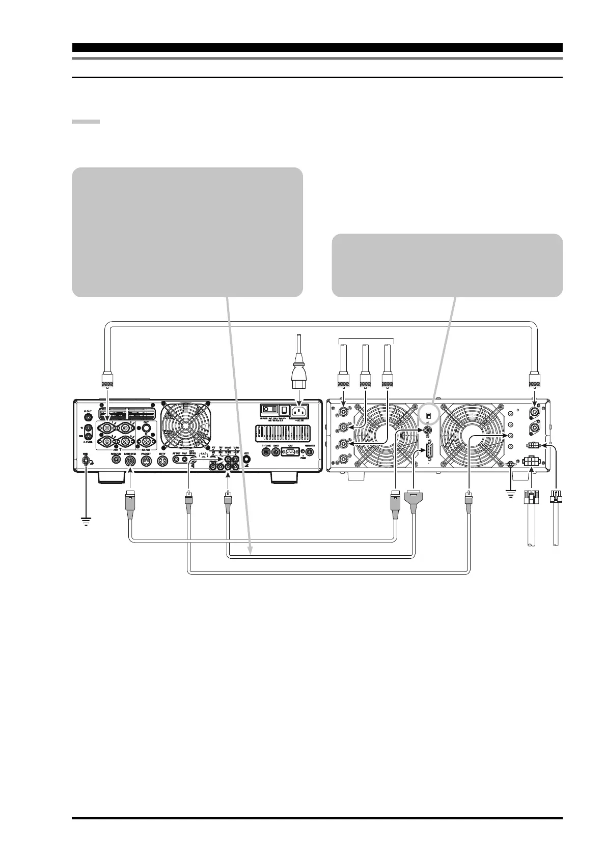
VL-1000 LINEAR AMPLIFIER INTERCONNECTIONS
Be sure both the FTDX5000 and VL-1000 are turned off, then follow the installation recommendations contained in the
illustration.
NOTE:
Refer to the VL-1000 Operating Manual for details regarding amplifier operation.
Do not attempt to connect or disconnect coaxial cables when your hands are wet.
INSTALLATION AND INTERCONNECTIONS
About the CONTROL Cable
The VL-1000 may be operated with the
FTDX5000 whether or not the CONTROL Cable
is connected; however, the CONTROL Cable
allows you to tune up the amplifier automatically
by just pressing the [F SET] or [TUNE] key on
the VL-1000, to transmit a carrier for tuning pur-
poses.
To link the FTDX5000 and VL-1000 Power
switches, set the VL-1000 REMOTE switch to
the “ON” position.

 Loading...