Page 35FTDX5000 OPERATING MANUAL
REAR PANEL CONNECTIONS
MIC
(
PATCH
)
Jack
This RCA input jack accepts either AFSK or voice
audio, for transmission. This line is mixed with the mi-
crophone audio input line, so the microphone should
be disconnected if using this jack and mixing is not
desired. The optimum impedance is 500 ~ 600 Ohms,
and the nominal input level should be 5 mV.
REC Jack
This RCA jack provides low-level receiver audio out-
put and transmit (monitor) audio (requires the
[
MONI
]
button is turned on), for external recording or external
amplification. Peak signal level is 30 mVp-p at 10 k-
Ohms.
TX REQ Jack
When this RCA jack is shorted to ground, it puts the
transceiver into the transmit mode, and sends out a
steady CW carrier, for linear amplifier or manual an-
tenna tuner adjustment.
+13.8 V Jack
This RCA output jack provides regulated, separately
fused 13.8 VDC at up to 200 mA, to power an external
device such as a packet TNC. Make sure your device
does not require more current (if it does, use a separate
power source).
KEY Jack
This 1/4-inch, 3-contact jack accepts a CW key or keyer
paddle. Key-up voltage is +5 V, and key-down current
is 1 mA. Plug wiring is shown on page 15, and the jack
may be configured for keyer, “Bug,” “straight key,” or
computer keying interface operation via Menu item
“059 A1A R-TYPE.”
NOTE:
You cannot use a 2-contact plug in this jack (to do
so produces a constant “key down” condition).
Main Power Switch
This is the main power “on”
(
I
)
/“off”
(
O
)
switch of the
transceiver. Always turn this switch on before turning
on the front panel
[
POWER
]
button.
If this switch is not turned “on”, the front panel
[
POWER
]
switch will not function.
Circuit Breaker Switch
This circuit breaker shuts off in the event of danger-
ously high current consumption by the transceiver.
ADVICE:
If the Circuit Breaker interrupts power, by all means
try to determine the cause of the over-current condi-
tion before re-applying power. To restore the Circuit
Breaker after verifying that all is normal, push the
switch in until you hear a “click”.
~AC IN Jack
Connect the supplied 3-wire AC line cord to this socket.
AC voltages of 100-240 V may be accommodated by
the transceiver without any sort of modification (uni-
versal voltage input).
µ-TUNE Jack
This 10-pin MINI-DIN jack is used for control of the
optional RF µTuning Kits.
DMU Jack
This 8-pin MINI-DIN jack accepts a cable connected
to an optional DMU-2000 Data Management Unit or
SM-5000 Station Monitor.
CAT Jack
This 9-pin serial DB-9 jack allows external computer
control of the transceiver. Connect a serial cable here
and to the RS-232C COM port on your personal com-
puter (no external interface is required).
PGM
(
PROGRAM
)
Switch
This slide switch is used for updating the transceiver’s
firmware. The update software and instructions are
available for download from the Vertex Standard
website (http://www.yaesu.com/).
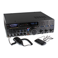
REMOTE Jack
By plugging the supplied FH-2 Remote Control Key-
pad into this jack, direct access to the CPU is provided,
for control of functions such as the audio playback fea-
ture, and the contest memory keyer, plus frequency and
function control.
 Loading...
