n
Input Voltage Setting Value: E1-01
The
input
voltage
level
determines
the
overvoltage
detection level and the operation level of
the braking transistor as shown in the table below.
Voltage
Setting Value of
E1-01
(Approximate Values)
ov Detection
Level
Braking Transistor
Operation Level
Uv Detection Level
200 V Class All settings 410 V 394 V
190 V
(single-phase=160 V)
400 V Class
Setting ≥ 400V 820 V 788 V 380 V
Setting < 400V 740 V 708 V 350 V
Note: This data is for an internal dynamic braking resistor of 0.1 to 18.5 kW. For larger units, see “Dynamic
Braking Resistor Unit for VARISPEED-600 Series, TOBPC72060000.”
u
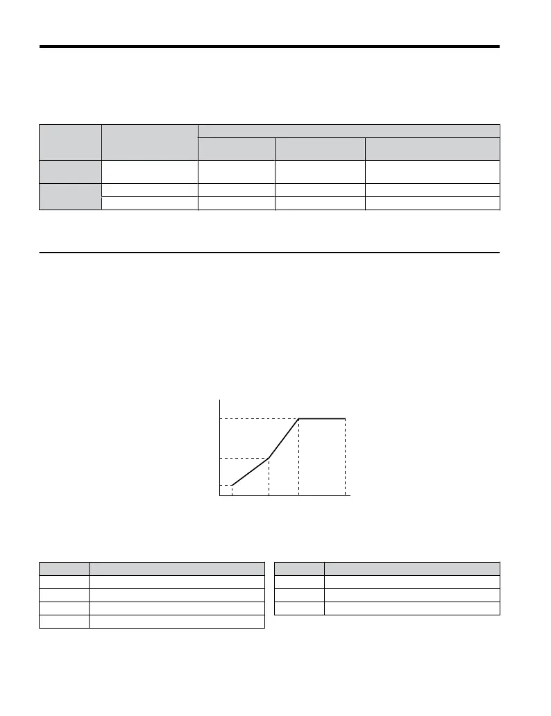
V/f Pattern Settings: E1-04 to E1-10
Depending on the application, it may be necessary to adjust the V/f pattern. Figure 4.16
illustrates parameters that need to be set up to adjust the V/f pattern characteristics.
n
Instructions for Setting a V/f Pattern
1.
Set the input voltage for the drive. Refer to Drive Input Voltage Setting: E1-01 on
page 99.
2.
Set the V/f pattern:
E1-05
E1-08
E1-10
E1-09 E1-07 E1-06 E1-04
Frequency (Hz)
Output Vol (V)
Figure 4.16 V/f Pattern
No. Parameter Name
E1-04 Maximum Output Frequency
E1-05 Maximum Voltage
E1-06 Base Frequency
E1-07 Mid Output Frequency
No. Parameter Name
E1-08 Mid Output Frequency Voltage
E1-09 Minimum Output Frequency
E1-10 Minimum Output Frequency Voltage
4.5 Basic Operation
100
YASKAWA ELECTRIC TOEP C710606 25B YASKAWA AC Drive J1000 Installation & Start-Up Manual
2/6/2008-14:44

 Loading...


