• Disable motor protection (L1-01 = 1) when running multiple motors from the same drive.
Attach a thermal relay for each motor to provide overload protection.
• Use L1-13 (Continuous Electrothermal Operation Selection) to select whether the
electrothermal value is “held” or “not
held” when power supply is turned off. Default setting
is 1 (Enabled).
• In the case of a general purpose (standard) motor, the cooling capability is reduced at a low
speed. Motor overload protection (oL1) may occur in frequencies lower than motor rated
current. Use an exclusive-use or inverter-duty motor to operate the drive at rated current at
low frequency.
u
Notes on Controlling the Brake for the Hoist Application
• The frequency detection function is used for controlling the brake.
When an external Baseblock command is present while a Run command is active, the
frequency reference will be kept as long as the Run command is active. To avoid improper
brake operation make sure that frequency detection is set so that the brake does not open
during Baseblock (L4-07 = “0”, default).
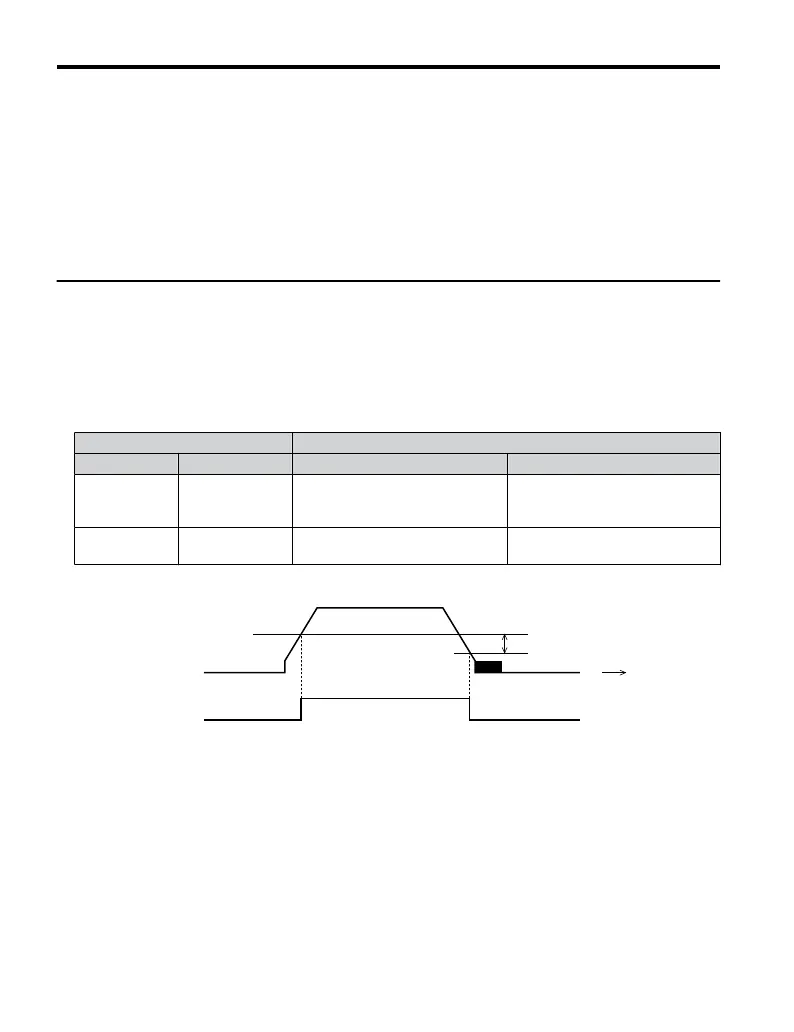
Brake Open/Close Brake Activation Level
Function Parameter Signal Parameter
Frequency
Detection
Conditions
L4-07 = 0 Frequency Detection Level
L4-01 = 2.0 to 3.0 Hz
<1>
Frequency
Detection 2
H2-01 = 5 Frequency Detection Width 2.0 Hz (fixed)
<1> If the load slips during stop, make it greater than E1-09 or 2.0 Hz until the load no longer slips.
2.0 Hz (fixed)
L4-01
OFF
ON
Time
Output
Frequency
Frequency
Dectection 2
Figure 4.20 Frequency Detection 2
• The braking sequence should be designed as follows:
• A normally open signal (N.O.) should be used to control the brake so that it is released
when terminal MA-MC closes.
• When an Up or Down command is entered, the brake should release.
• When a fault signal is output, the brake should close.
• When changing the
speed using an analog signal, make sure that the source of the frequency
reference is assigned to the control circuit terminals (b1-01 = 1).
4.5 Basic Operation
108
YASKAWA ELECTRIC TOEP C710606 25B YASKAWA AC Drive J1000 Installation & Start-Up Manual
2/6/2008-14:44

 Loading...


