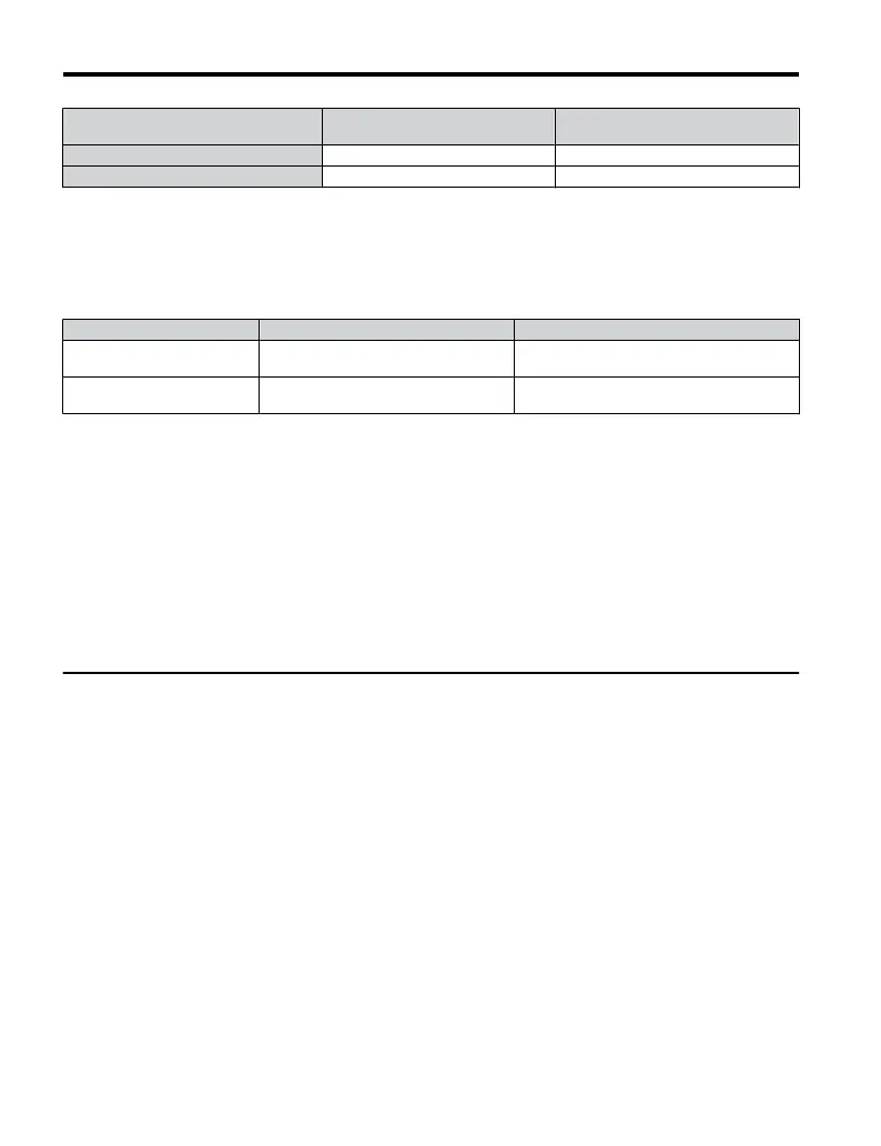
Drive Model CIMR-Jo
Class T Fuses
600 Vac, 200 kAIR
Fuse Ampere Rating
4A0009 A6T25 25
4A0011 A6T30 30
n
Low Voltage Wiring for Control Circuit Terminals
Wire low voltage wires with NEC Class 1 circuit conductors. Refer to national state or local
codes
for
wiring.
Use
a
class
2
(UL regulations) power supply for the control circuit terminal.
Table C.6 Control Circuit Terminal Power Supply
Input / Output Terminal Signal Power Supply Specifications
Multi-function digital inputs S1, S2, S3, S4, S5, SC
Use the internal power supply of the drive.
Use class 2 for external power supply.
Main frequency reference +V, A1, AC
Use the internal power supply of the drive.
Use class 2 for external power supply.
n
Drive Short-Circuit Rating
This drive has undergone the UL short-circuit test, which certifies that during a short circuit
in
the
power
supply
the
current
flow
will not rise above 30,000 amps maximum at 240 V for
200 V class drives and 480 V for 400 V class drives.
• The MCCB and breaker protection and fuse ratings shall be equal to or greater than the
short-circuit tolerance of the power supply being used.
• Suitable for use on a circuit capable of delivering not more than 30,000 RMS symmetrical
amperes for 240 V in 200 V class drives (up to 480 V for 400 V class drives) motor overload
protection.
u
Drive Motor Overload Protection
Set parameter E2-01 (motor rated current) to the appropriate value to enable motor overload
protection. The internal motor overload protection is UL listed and in accordance with the
NEC and CEC.
n
E2-01 Motor Rated Current
Setting Range: Model Dependent
Default Setting: Model Dependent
Parameter E2-01 (motor rated current) protects the motor if parameter L1-01 is not set to 0
(default is 1, standard induction motor protection enabled).
C.3 UL Standards
238
YASKAWA ELECTRIC TOEP C710606 25B YASKAWA AC Drive J1000 Installation & Start-Up Manual
2/6/2008-14:44

 Loading...


