No. Name Description Range Def.
Mode
Addr.
Hex
Pg.
V/f
o4-09
IGBT
Maintenance
Setting
Sets the value of the IGBT Maintenance monitor
U4-07.
0 to 150 0% O 525 —
o4-11
U2 Initialize
Selection
Selects if U2-oo (Fault Trace) monitors are reset at
drive initialization.
0: Saves the fault monitor data
1: Resets the fault monitor data
0, 1 0 O 510 —
<12> Default setting value is dependent on parameter o2-04, Drive Model Selection.
<22>
Parameter can be changed during run.
<61>
Valid for drive software 1011 and later. Value is set in 1 h units for older software.
u
U: Monitors
Monitor parameters allow the user to view drive status, fault information, and other
information about drive operation.
No. Name Description
Analog
Output Level
Unit
Mode
Addr.
Hex
V/f
U1: Operation Status Monitors
Use U1 monitors to display the operation status of the drive.
U1-01
Frequency
Reference
Monitors the frequency
10 V: Max
frequency
0.01
Hz
O 40
U1-02
Output
Frequency
Displays the output frequency. Display units are
determined by o1-03.
10 V: Max
frequency
0.01
Hz
O 41
U1-03
Output
Current
Displays the output current.
10 V: Drive
rated current
0.01
A
O 42
U1-06
Output
Voltage
Reference
Displays the output voltage.
10 V: 200 Vrms
(400 Vrms)
0.1 V O 45
U1-07
DC Bus
Voltage
Displays the DC bus voltage.
10 V: 400 V (800
V)
1 V O 46
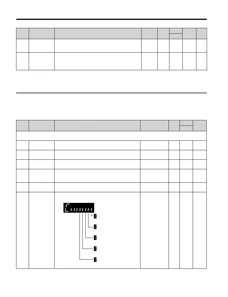
U1-10
Input Terminal
Status
Displays the input terminal status.
Digital input terminal
S1 enabled
Digital input terminal
S2 enabled
Digital input terminal
S3 enabled
Digital input terminal
S4 enabled
Digital input terminal
S5 enabled
No output signal
available
– O 49
B.2 Parameter Table
216
YASKAWA ELECTRIC TOEP C710606 25B YASKAWA AC Drive J1000 Installation & Start-Up Manual
2/6/2008-14:44

 Loading...


