3.9 Main Frequency Reference
u
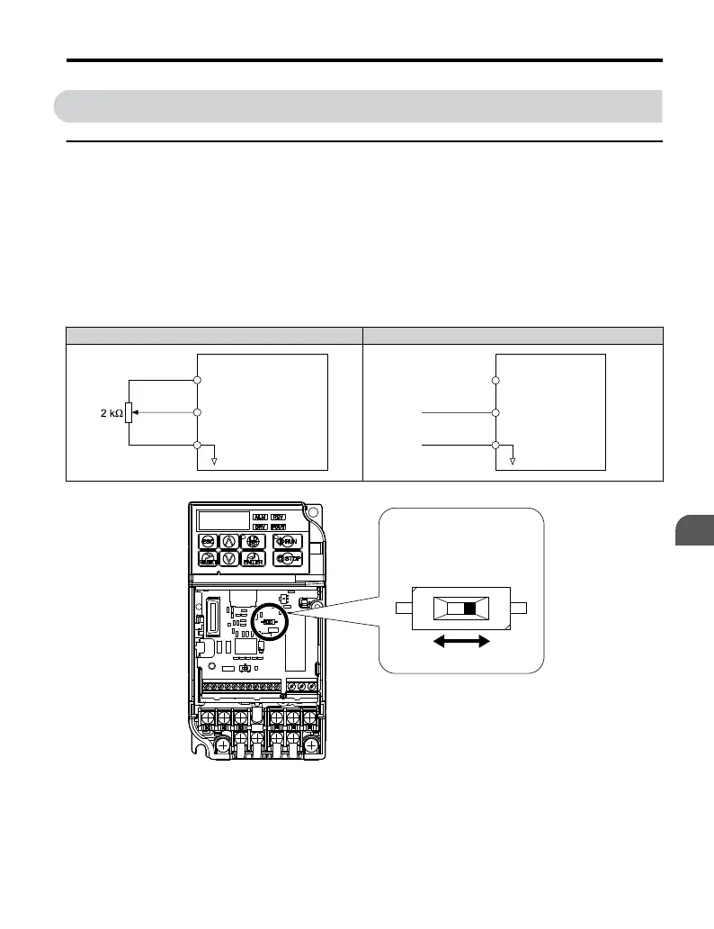
DIP Switch S1 Analog Input Signal Selection
The main frequency reference can either be a voltage or current signal input.
To use current input at terminal A1, set the DIP switch S1 to "I" (default setting) and set
parameter H3-01 = “2” or “3” (4-20 mA or 0-20 mA).
When using as a voltage input, set DIP switch S1 to “V” (right position) and program
parameter H3-01 to “0” (0 to +10 Vdc with lower limit) or “1” (0 to +10 Vdc without lower
limit).
Table 3.11 Frequency Reference Configurations
Voltage Input Current Input
+10.5 V
20 mA current
Main speed frequency
reference (voltage input)
Frequency reference
common
Drive
+V
A1
AC
0 to 10 V
+10.5 V
20 mA current
Main speed
frequency reference
(current input)
Frequency
reference
common
+V
A1
AC
Drive
4 to 20 mA input
or
0 to 20 mA input
I V
DIP Switch S1
Figure 3.19 DIP Switch S1
3.9 Main Frequency Reference
YASKAWA ELECTRIC TOEP C710606 25B YASKAWA AC Drive J1000 Installation & Start-Up Manual
63
3
Electrical Installation
2/6/2008-14:44

 Loading...


