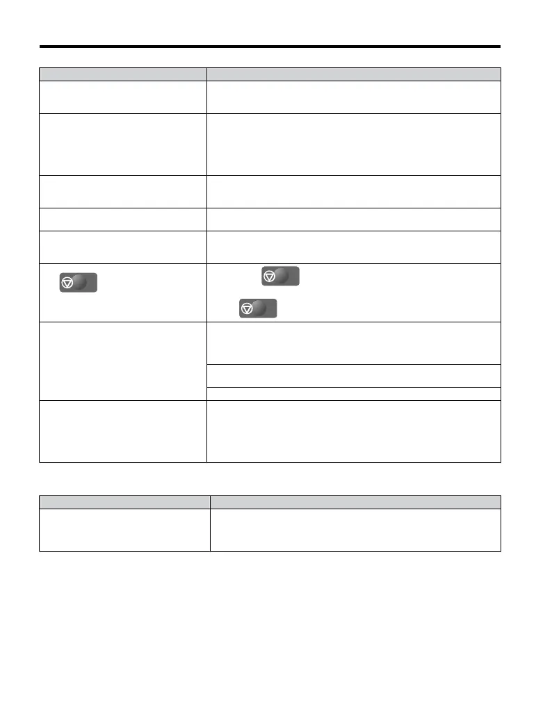
Cause Possible Solutions
There is faulty wiring in the control circuit
terminals.
• Check the wiring for the control terminal.
• Correct wiring mistakes.
• Check the input terminal status monitor (U1-10).
The drive has been set to accept the
frequency reference from the incorrect
source.
Check parameter b1-01 (Frequency Reference Selection 1).
Set b1-01 to the correct source of the frequency reference.
0: LED operator
1: Control circuit terminal (default setting)
2: MEMOBUS/Modbus communications
3: Potentiometer (option)
The terminal set to accept the main speed
reference is set to the incorrect voltage
and/
or current.
Check DIP switch S1. Next assign the correct input level to terminal A1
(H3-01).Refer to DIP Switch S1 Analog Input Signal Selection on page
63.
Selection for the sink/source mode is
incorrect.
Check DIP switch S3. Refer to Sinking/Sourcing Mode Switch on page
60.
Frequency reference is too low.
• Check the frequency reference monitor (U1-01).
• Increase the frequency by changing the maximum output frequency
(E1-09).
The
STOP
button was pressed when
the drive was started from a REMOTE
source. .
•
When the
STOP
button is pressed, the drive will decelerate to stop.
• Switch off the run command and then re-enter a run command.
•
The
STOP
button is disabled when o2-02 is set to 0.
Motor is not producing enough torque.
• Ensure the selected V/f pattern corresponds with the characteristics of
the motor being used.
• Increase both the minimum and mid output
frequency voltages (E1-08,
E1-10).
Increase the frequency reference so that it is higher than the minimum
frequency reference (E1-09).
Increase the torque compensation gain (C4-01).
The drive is set for both 2-Wire and 3-Wire
sequence at the same time.
• The drive is set for a 3-Wire sequence when one of parameters H1-03
through H1-05 is set to 0.
• If the drive is supposed to be set up for a 2-Wire sequence, then ensure
parameters H1-03 through H1-05 are not set to 0.
• If the drive is supposed to be set up for a 3-Wire sequence, then H1-
oo must be set to 0.
n
Motor Rotates in the Opposite Direction from the Run Command
Cause Possible Solutions
Phase wiring between the drive and motor
is incorrect.
• Check the motor wiring.
• Switch two motor cables (U, V, and W) to reverse motor direction.
• Connect drive output terminals U/T1,
V/T2 and W/T3 in the right order
to the corresponding motor terminals U, V, and W.
5.8 Troubleshooting without Fault Display
144
YASKAWA ELECTRIC TOEP C710606 25B YASKAWA AC Drive J1000 Installation & Start-Up Manual
2/6/2008-14:44

 Loading...


