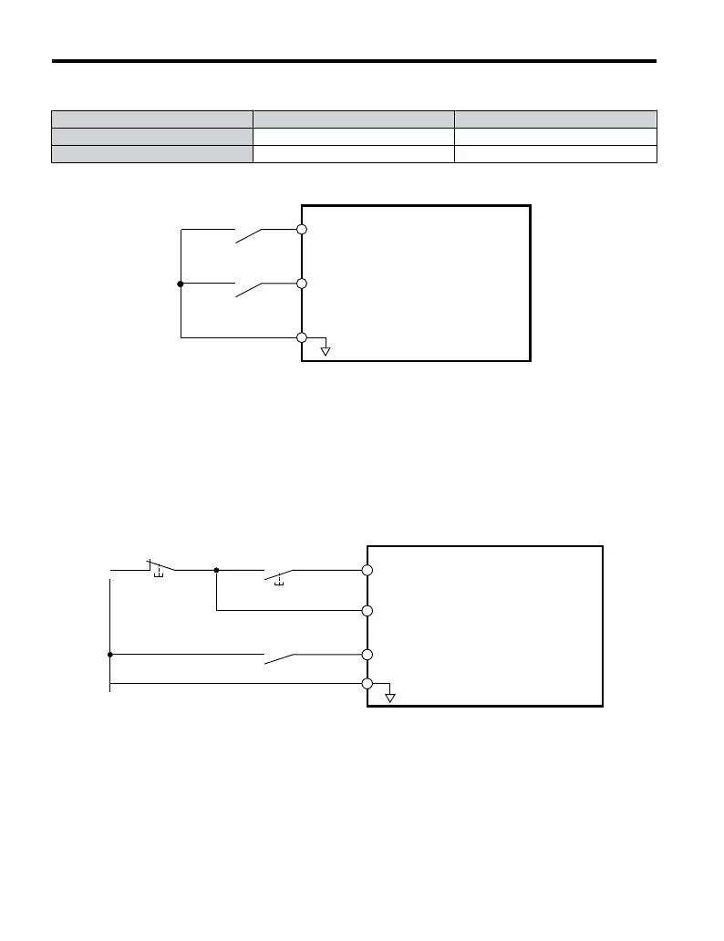
Using a 2-Wire Sequence
Digital Input Terminals ON OFF
S1 Forward Run Stop
S2 Reverse Run Stop
S1
S2
SC
Drive
Forward Run
Reverse Run
Digital Input Common
Figure 4.9 Example Wiring Diagram for 2-Wire Sequence
Using a 3-Wire Sequence
When H1-05 (Multi-Function Digital Input Terminal S5
Function Selection) = 0, the functions
of terminals S1 and S2 are set to 3-wire sequence, and the multi-function input terminal
becomes forward/reverse run command terminal.
S1
S2
S5
SC
Run Command
Runs when S1 and S2 are closed
Drive
Stop Button
(N.C.)
Run Button
(N.O.)
Stop Command
Stops when S1 and S2 are open
FWD/REV Command
<1>
Digital Input Common
(Run button pushed)
(Stop button pushed)
Figure 4.10 Example Wiring Diagram for 3-Wire Sequence Using Terminal S5
<1> When terminal S5 is open, the motor rotates forward. When closed, the motor rotates in
reverse.
4.5 Basic Operation
90
YASKAWA ELECTRIC TOEP C710606 25B YASKAWA AC Drive J1000 Installation & Start-Up Manual
2/6/2008-14:44

 Loading...


