Body
Body 60-19
60
Side Fairings (Inner)
NOTICE: Before carrying out any work on the
electrical system, remove the key from the key
switch.
Tools Required (includes tools required for
parent jobs):
• T25
• T30
• 2mm hex wrench
• 3/16” standard screwdriver
• 10mm socket and ratchet
New Fasteners Required:
• Cable tie (quantity: 2)
Removal
1. PERFORM LOCKOUT PROCEDURE: See
Lockout Procedure
, page 10.1.
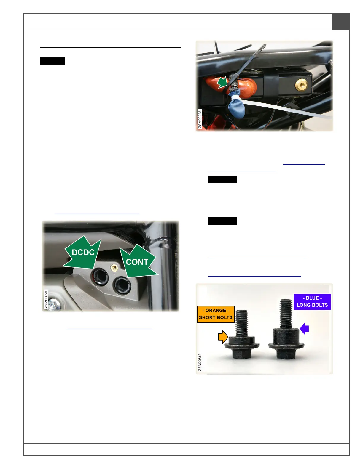
2. Remove high voltage DCDC and CONT fuses.
See High Voltage Fuses
, page 70.1.
3. Unbolt the negative battery terminal eyelet.
Cover eyelet with insulating material. Use
cable tie to secure negative battery wire to the
positive battery cable. See 12 Volt Battery
(Disconnect), page 70.3.
CAUTION: Cover/protect battery terminal
eyelet to reduce the risk of accidentally
contacting the negative battery terminal,
which can inadvertently power up the
12 volt system and damage components.
CAUTION: Secure battery terminal wire to
reduce the risk of arcing and damaging
electrical components.
4. Remove headlight upper fairing. See
Headlight Upper Fairing
, page 60.2.
5. Remove left and right outer side fairings. See
Side Fairings (Outer)
, page 60.14.
6. For the rest of this procedure, there will be
references to shouldered-bolts securing body
panels, that are 2 different lengths.
Short bolts: designated on photos with
orange arrows, used to attach a single body
panel layer.
 Loading...