Power Pack
Power Pack 20-1
20
Power Pack
Power Pa ck
Power Pack
Tools Required (includes tools required for
parent jobs):
• T20
• T25
• T27
• T30
• T40
• 3/16” standard screwdriver
• 2mm hex wrench
• 7mm combination wrench
• 10mm socket and ratchet
• 22mm 6-point socket
• Non-marring trim removal/pry tool
• O-ring pick
• Scissor jack
• Ratchet straps (x2)
• Hoist
Zero Motorcycles Specialty Tools Required
(includes tools required for parent jobs):
• Power Pack fixture
New Seals Required:
• Controller cable seals (quantity: 5)
• Controller cable O-rings (quantity: 5)
New Fasteners Required:
• Cable ties (quantity: 3)
• Double loop cable tie (quantity: 1)
Removal
1. PERFORM LOCKOUT PROCEDURE: See
Lockout Procedure, page 10.1.
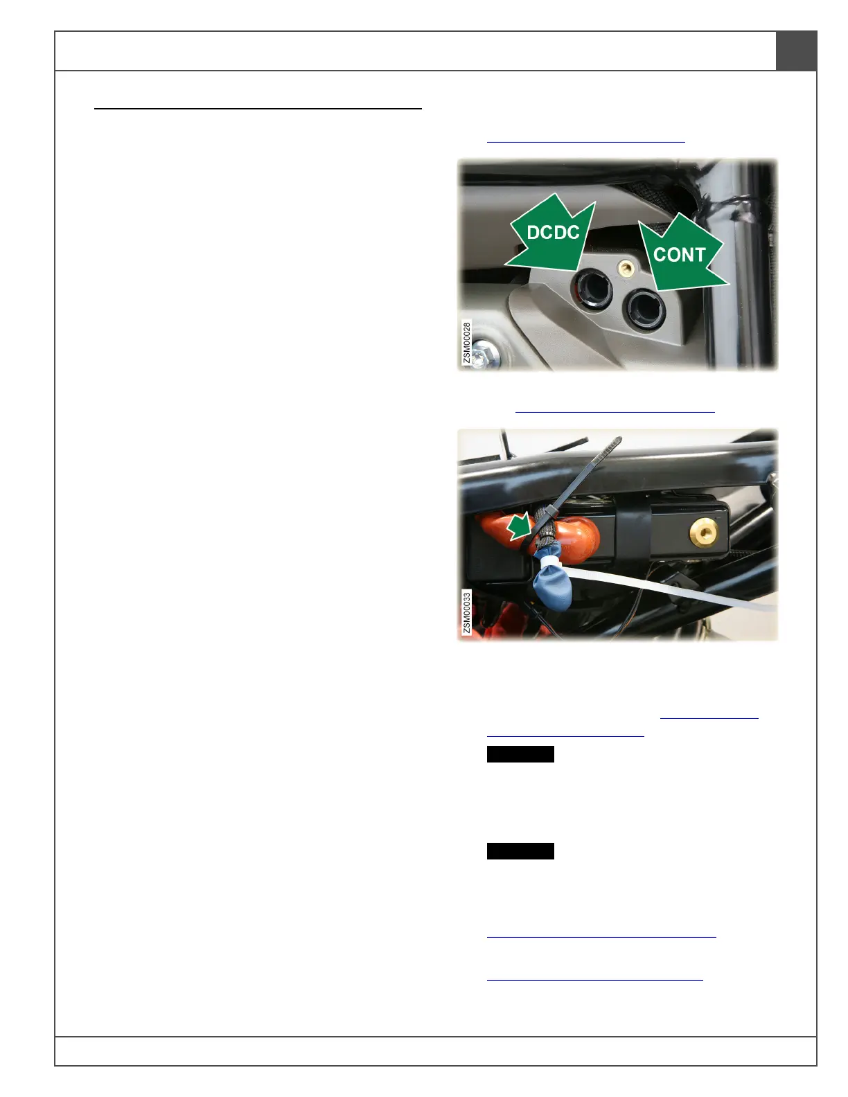
2. Remove high voltage DCDC and CONT fuses.
See High Voltage Fuses, page 70.1.
3. Unbolt the negative battery terminal eyelet.
Cover eyelet with insulating material. Use
cable tie to secure negative battery wire to the
positive battery cable. See 12 Volt Battery
(Disconnect), page 70.3.
CAUTION: Cover/protect battery terminal
eyelet to reduce the risk of accidentally
contacting the negative battery terminal,
which can inadvertently power up the
12 volt system and damage components.
CAUTION: Secure battery terminal wire to
reduce the risk of arcing and damaging
electrical components.
4. Remove headlight upper fairing. See
Headlight Upper Fairing, page 60.2.
5. Remove left and right outer side fairings. See
Side Fairings (Outer), page 60.14.

 Loading...