Operation Manual / A200-L
9 Disassembly and assembly / 9.20 Fitting wall insert
© Copyright 2021 ABB. All rights reserved. HZTL4036_EN Rev.T December 2021
A255-L.. - A260-L..
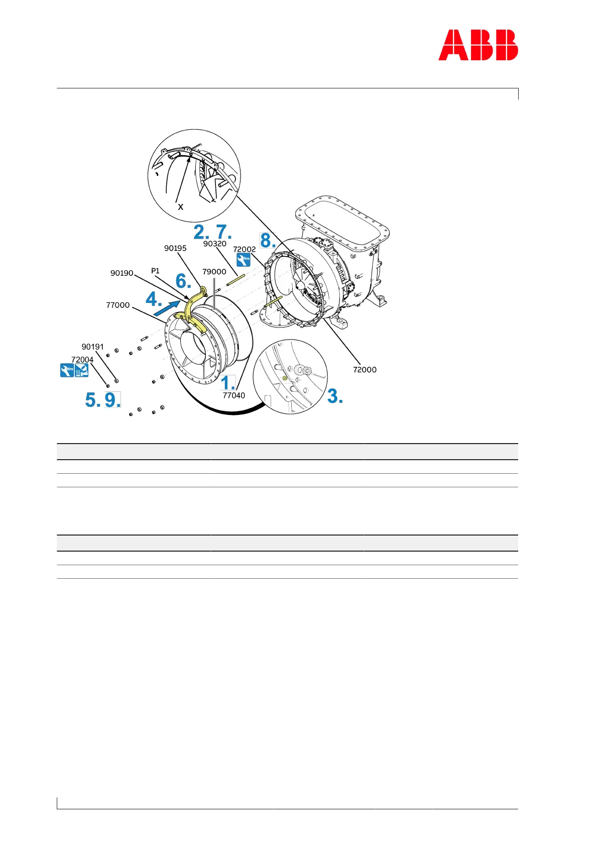
Fig.60: Fitting the wall insert (A255-L.. - A260-L..)
Product Size Tightening torque [Nm]
A255-L M16 60
A260-L M16 60
Table40: Tightening torque(72002)
Product Size Tightening torque [Nm]
A255-L M16 265
A260-L M16 265
Table41: Tightening torque (72004)
1. Attach the new O-ring(77040) to the wall insert(77000).
2. Fit two guide studs (90320) in the upper area of the compressor casing (72000). Leave
the top threaded hole (x) in the compressor casing empty.
3. Align arrow markings of wall insert(77000) and compressor casing to one another.
4. Carefully move the wall insert with diffuser(79000) over the guide studs into the com-
pressor casing. Check the correct alignment of the wall insert and the compressor cas-
ing.
5. Fit a hexagon nut (72004) with a sleeve (90191) as a safety device.
6. Remove the shackle (90195) with lifting gear. Fit shackle with lifting gear on P1 of the lift-
ing device (90190) and remove with the crane.
Page 102 / 145
 Loading...