ACS2000 User manual 2UEA001270 Rev. F 6-9 (16)
Chapter 6 - Electrical installation
6.6 Line supply and motor cables
6.6.1 Further information
See Layout drawing in Appendix D - Mechanical drawings, located on the
CD, for information on:
• Project specific cable entry
• Distance between point of cable entry and termination bars
See Appendix E - Wiring diagrams, located on the CD, for information on:
• Designation, cross-reference and device-identification conventions
6.6.2 Cable preparation
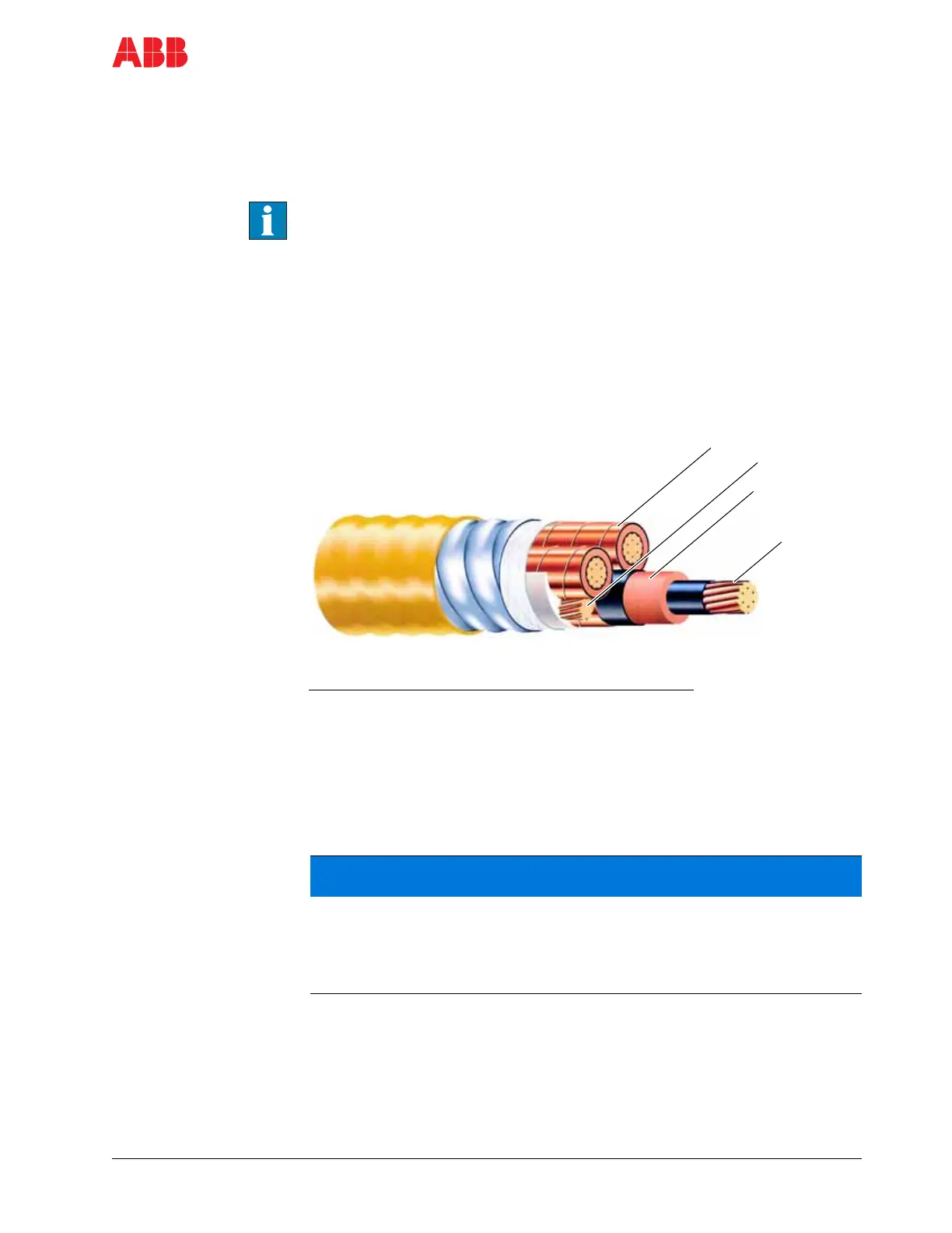
Figure 6-6 Typical line and motor cable
6.6.2.1 Determining the cable length
If possible, do not cut cables inside the terminal entry unit. Make sure that
waste from cable cutting and stripping cannot enter the cabinet. Any waste
which is accidentally dropped into the cabinet must be removed. The
waste could cause damage or malfunction.
Enter the cables into the terminal entry unit to measure the conductor
length.
Mark the required conductor length, withdraw the cable and cut it to the
correct length.
1
Legend
1 Copper shield
2 Ground conductor
3 Insulation
4 Copper conductor
2
3
4
 Loading...


