2-8 (28) 2UEA001270 Rev. F ACS2000 User manual
Chapter 2 - Power electronics and cabinet features
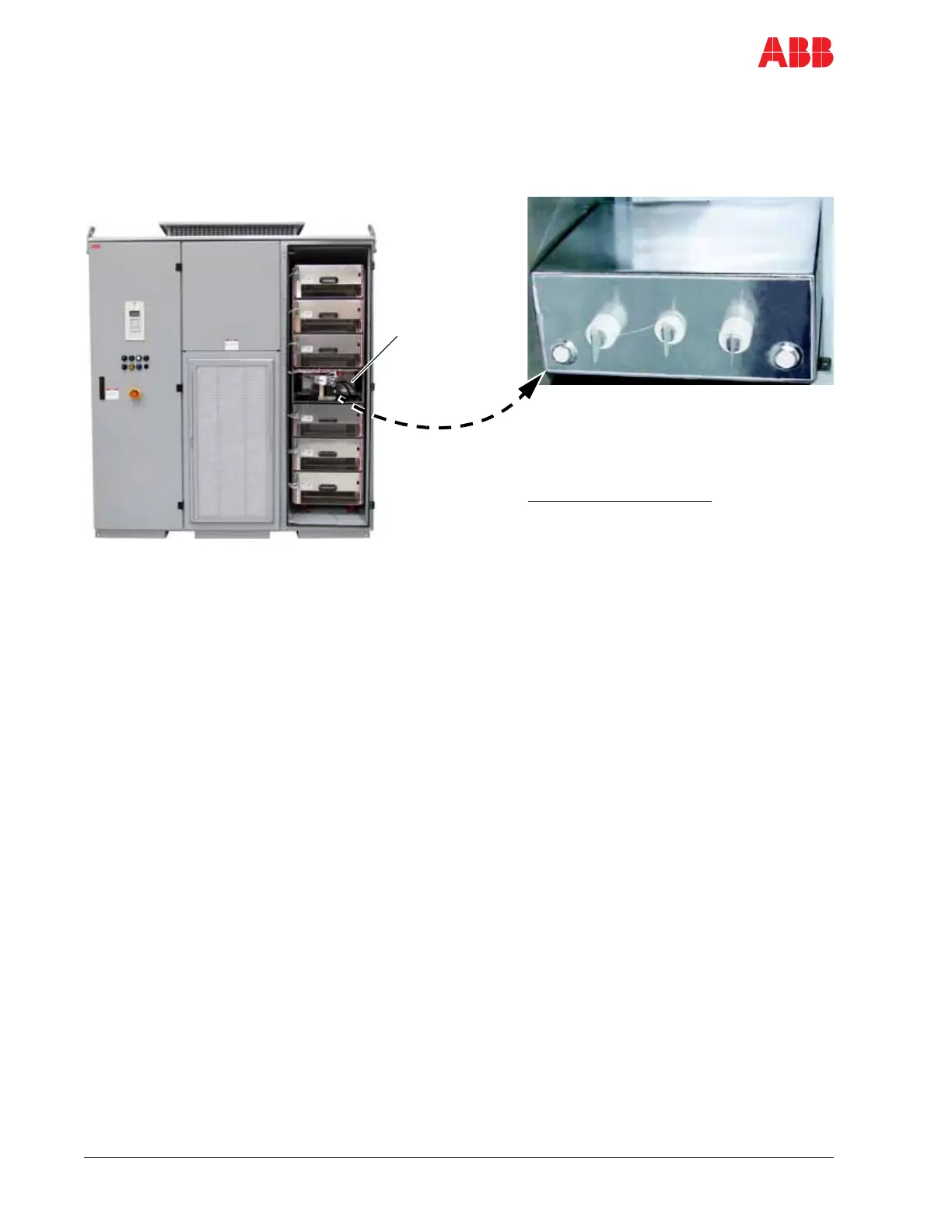
2.2.4 DC link
The DC link consists of the capacitor, the charging unit and the grounding
switch. The capacitor is oil-filled and features self-healing technology.
Figure 2-6 DC link capacitor
2.2.4.1 Charging unit
The charging unit consists of the charging transformer and low and high
voltage relays.
Charging The charging unit is fed from the auxiliary power supply and charges the
DC link and the phase capacitors.
The unit charges the DC link capacitor and the phase capacitors before
the MV (Medium Voltage) switchgear is closed to connect the drive to the
main power supply. This eliminates excessive inrush current when
connecting to the MV supply.
The charging sequence is started by pressing the SUPPLY ON
pushbutton on the control compartment door. After the charging sequence
has finished, the charging unit is disconnected from the medium voltage
circuit, the MV switchgear is closed and the DC link will reach its nominal
level. Typical time from pressing the SUPPLY ON pushbutton to
completion of the pre-charge sequence is approximately 10 seconds for
Frame 1 (see Table 2-1).
Discharging Discharging is initiated by pressing the SUPPLY OFF pushbutton on the
control compartment door, which opens the MV switchgear. The DC link
capacitors will then discharge via active modulation. The energy stored in
the capacitors is dissipated in the clamping resistors of the power part of
the drive. When the DC link voltage has decreased below 25% of its
nominal value, the capacitor in the phase modules begin to discharge.
Legend
1 DC link capacitor
1
 Loading...


