ACS2000 User manual 2UEA001270 Rev. F 3-17 (26)
Chapter 3 - Control system
3.3.2.2 IOEC2 (A1541) digital inputs
Table 3-5 Standard digital input signal allocation
Terminal Channel Default setting Par. Group
X11-1 DI01 External start/stop request 72.06 to
72.09
X11-2 Common
X11-3 DI02 Forward/reverse 72.10 to
72.11
X11-4 Common
X11-5 DI03 Freely programmable —
X11-6 Common
X11-7 DI04 Ramp 1/2 72.41 to
72.42
X11-8 Common
X11-9 DI05 Ext1/Ext2 30 to
31
X11-10 Common
X12-1 DI06 Constant speed select 24 to
25
X12-2 Common
X12-3 DI07 External on request (start DC link charge) 72.02 to
72.03
X12-4 Common
X12-5 DI08 Process stop (stops drive) 72.43 to
72.44
X12-6 Common
X12-7 DI09 MV switchgear open *
X12-8 Common
X12-9 DI10 MV switchgear closed *
X12-10 Common
X13-1 DI11 MV switchgear available (not tripped) *
X13-2 Common
X13-3 DI12 Remote reset 72.33 to
72.34
X13-4 Common
X13-5 DI13 External OFF request 72.04 to
72.05
X13-6 Common
X13-7 DI14 Disable local operation 72.35 to
72.36
X13-8 Common
X13-9 +24 V
+0 V
24 V control logic —
X13-10 Common
* Not configurable
When the integral input contactor disconnect is installed, these
signals are prewired.
Current
Signal level direct Typ 24 VDC
max 100 VDC
Signal level
alternating
Typ 24 VAC
max 230 VAC
Input 8...25mA
Inrush 24 V 10mA
Inrush 120 V Typ 65mA
max 100mA
1
2
3
4
5
6
7
8
9
10
X11
1
2
3
4
5
6
7
8
9
10
X12
1
2
3
4
5
6
7
8
9
10
X13
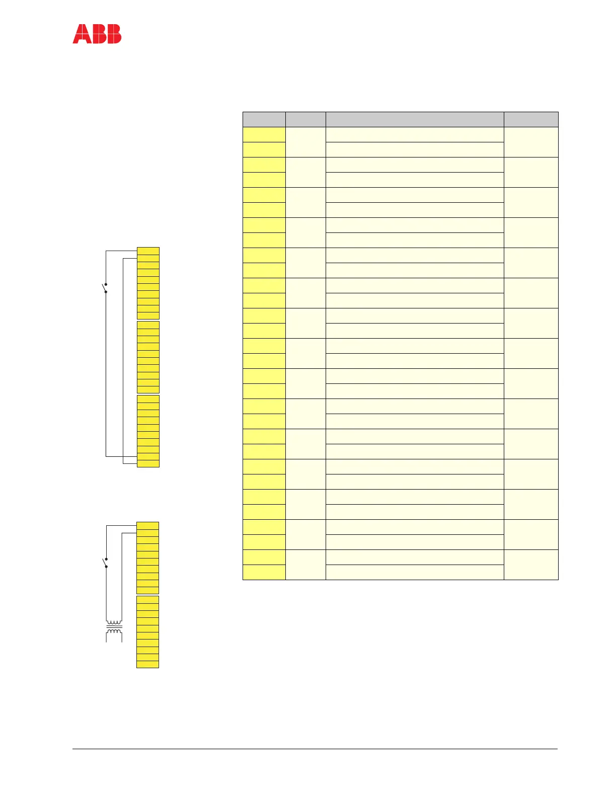
DI01
+24 V
0 V
Wiring example - start/stop switch
with 24 V internal supply
ExtStrReq
common
Remote
start/stop
Int. supply
1
2
3
4
5
6
7
8
9
10
X11
1
2
3
4
5
6
7
8
9
10
X12
DI01
Wiring example - start/stop switch
with external 120 V supply
ExtStrReq
common
Remote
start/stop
External
120 V
supply
 Loading...


