2-2 (28) 2UEA001270 Rev. F ACS2000 User manual
Chapter 2 - Power electronics and cabinet features
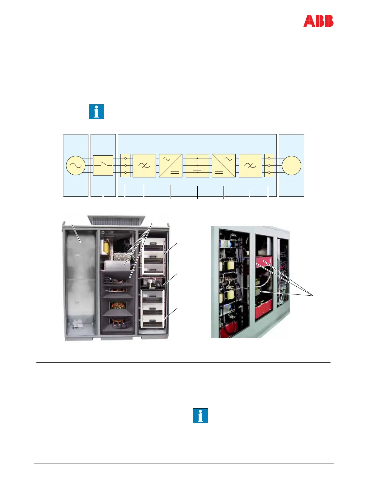
2.2 Drive topology
2.2.1 Topology
This section describes the main design features and introduces the major
power electronic components of a typical ACS2000 drive.
If you have ACS2000 with the integral input contactor disconnect option,
refer to Appendix P, section 2.4 Electrical installation, for topology
information.
Figure 2-2 - Frame 1 Overview
Legend
1 IFU - Input Filter Unit
2 AFE - Active Front End
3DC link
4 INU - INverter Unit
5dV/dt filter
6 TEU - Terminal Entry Unit for line and
motor cables (behind access panels)
7 Removable access panels for entry to TEU
8 Customer supplied isolating means –
typically a fused input contactor with visible
blade disconnect.
See Section 6.1.1 Isolating means (MV
Switchgear) and Appendix G - MV
switchgear guide, located on the CD,
for additional information.
1
Main
power
supply
ACS2000
TEUdV/dt
filter
INUDC linkAFEIFUTEU
6 2 3 4 5 6
M
4
3
2
Cabinet front
Cabinet rear
MV
switch-
gear
8
5
16, 7
 Loading...


