10-26 (32) 2UEA001270 Rev. F ACS2000 User manual
Chapter 10 - Troubleshooting and maintenance
10.4.8.3 Required tools and accessories
• Phase module tray tool - The phase module tray tool is shipped with
the new replacement phase module.
• Reversible ratchet with extension
• Phillips, Torx and slotted screwdrivers
• Cable tie
• 10 mm and 13 mm sockets
10.4.8.4 Phase module replacement procedure
Hazardous voltage! Dangerous voltage is present
when input power is connected.
Verify that the main power supply is switched off,
locked out and tagged out.
1 Disconnect upstream power using
the Kirk
®
key and perform generally
accepted Lockout-Tagout Proce-
dures.
WARNING! Dangerous voltage is present when input
power is connected. After disconnecting the supply,
wait until the ground RELEASED indicator lights up (to
let the intermediate circuit capacitors discharge) before
attempting to ground and open the AFE/INU
compartment door.
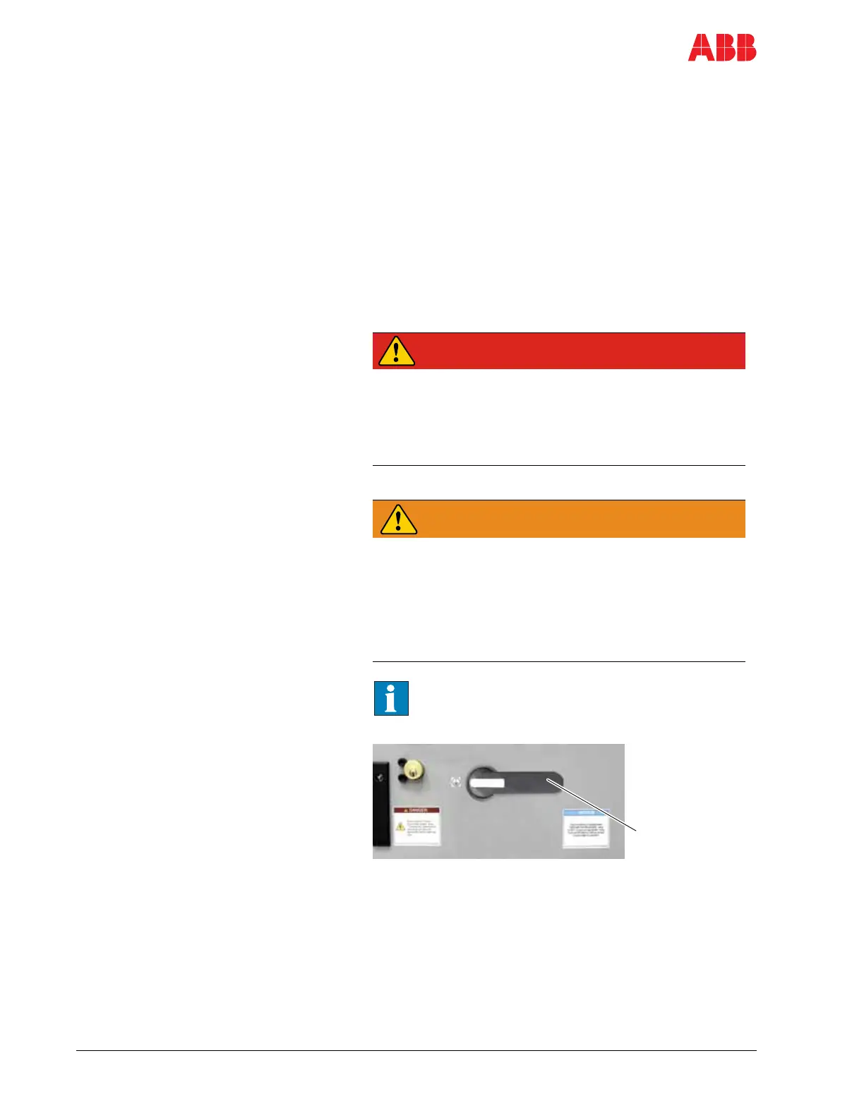
2 Turn the grounding switch to the
grounded position.
See Appendix P - Integral input contactor
disconnect, located on the CD, for Kirk key
location on drives with this option.
Open incoming cabinet and
perform Live-Dead-Live check on
incoming terminals. See Chapter 1
- Safety, section 8.7 De-energizing
the drive and Chapter 6 - Electrical
installation, if you need further
information.
Grounding
switch
(shown in
grounded
position)
 Loading...


