Program features 63
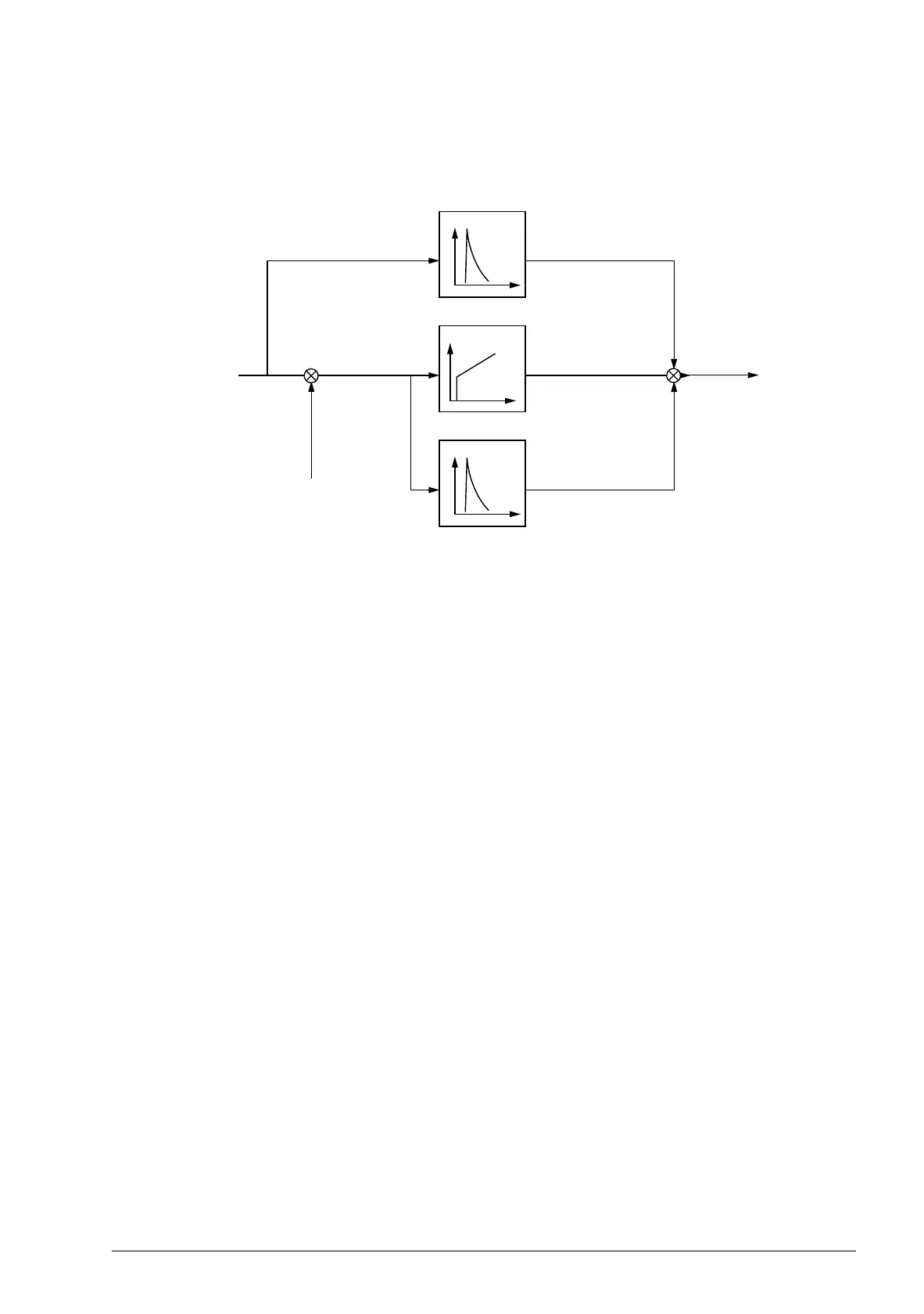
The figure below is a simplified block diagram of the speed controller. The controller
output is the reference for the torque controller.
Settings
Parameter group 23 Speed ctrl (page 176).
Encoder support
The program offers support for two encoders (or resolvers), encoder 1 and 2.
Multiturn encoders are supported only as encoder 1. Three optional interface
modules are available:
• TTL Encoder Interface FEN-01: two TTL inputs, TTL output (for encoder
emulation and echo) and two digital inputs for position latching
• Absolute Encoder Interface FEN-11: absolute encoder input, TTL input, TTL
output (for encoder emulation and echo) and two digital inputs for position latching
• Resolver Interface FEN-21: resolver input, TTL input, TTL output (for encoder
emulation echo) and two digital inputs for position latching.
• HTL Encoder Interface FEN-31: HTL encoder input, TTL output (for encoder
emulation and echo) and two digital inputs for position latching.
The interface module is connected to drive option Slot 1 or 2. Note: Two encoder
interface modules of the same type are not allowed.
Settings
Parameter groups 91 Absol enc conf (page 249), 92 Resolver conf (page 252) and 93
Pulse enc conf (page 252).
Derivative
Proportional,
integral
Derivative
acceleration
compensation
Tor q ue
reference
Speed
reference
Actual speed
Error
value
-
+
+
+
+
 Loading...


