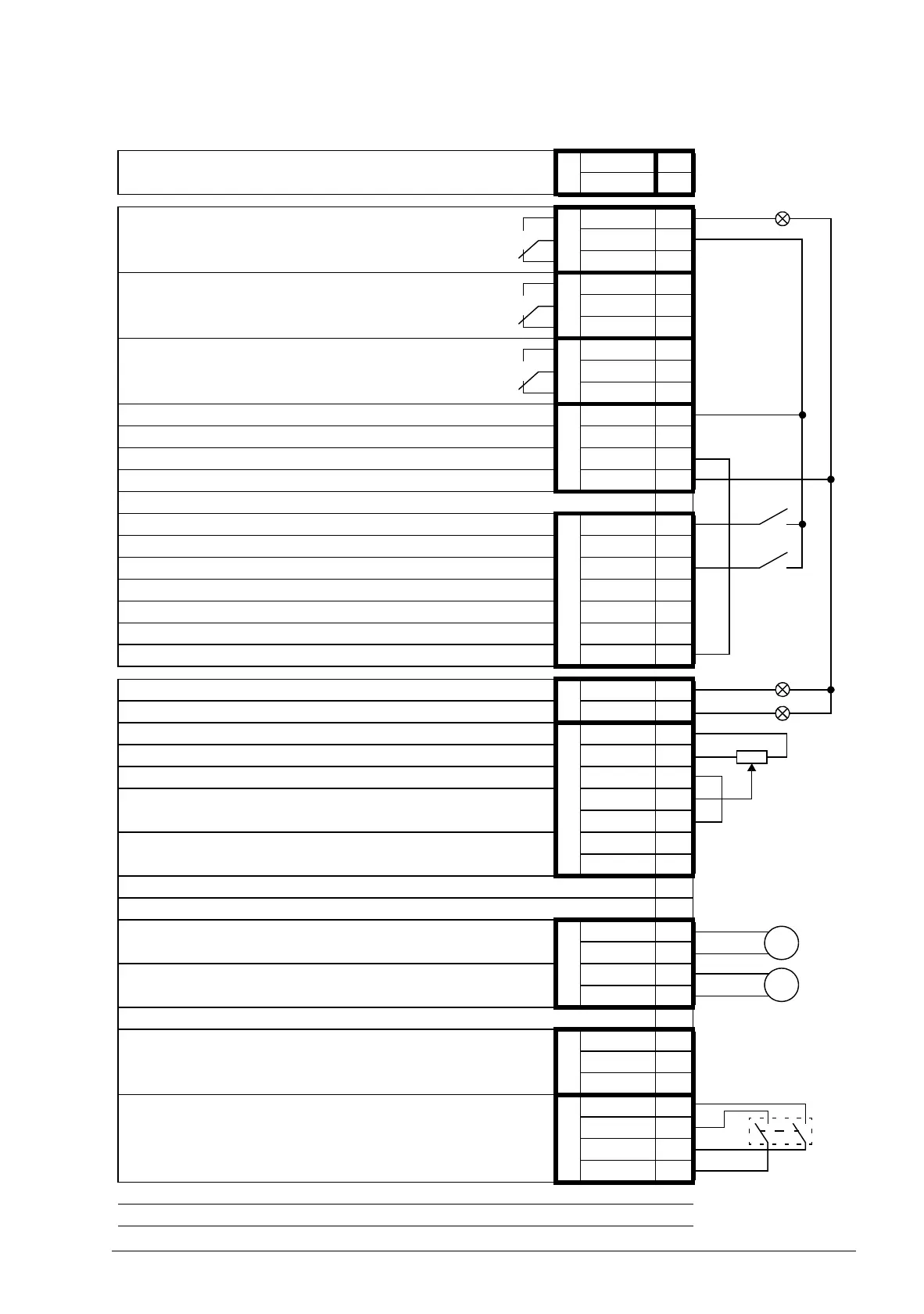
External power input
24 V DC, 1.6 A
XPOW
+24VI 1
GND 2
Relay output RO1 [Ready]
250 V AC / 30 V DC
2 A
XRO1
NO 1
COM 2
NC 3
Relay output RO2 [Modulating]
250 V AC / 30 V DC
2 A
XRO2
NO 4
COM 5
NC 6
Relay output RO3 [Fault (-1)]
250 V AC / 30 V DC
2 A
XRO3
NO 7
COM 8
NC 9
+24 V DC
XD24
+24VD 1
Digital input ground DIGND 2
+24 V DC +24VD 3
Digital input/output ground DIOGND 4
DI/DIO grounding selection jumpers
Digital input DI1 [Stop/Start]
XDI
DI1 1
Digital input DI2 DI2 2
Digital input DI3 [Reset] DI3 3
Digital input DI4 DI4 4
Digital input DI5 DI5 5
Digital input DI6 or thermistor input DI6 6
Start interlock (0 = Stop) DIIL A
Digital input/output DIO1 [Output: Ready]
XDIO
DIO1 1
Digital input/output DIO2 [Output: Running] DIO2 2
Reference voltage (+)
XAI
+VREF 1
Reference voltage (–) -VREF 2
Ground AGND 3
Analog input AI1 [Speed reference 1]
(Current or voltage, selectable by jumper AI1)
AI1+ 4
AI1- 5
Analog input AI2 (Current or voltage, selectable by jumper AI2)
AI2+ 6
AI2- 7
AI1 current/voltage selection jumper AI1
AI2 current/voltage selection jumper AI2
Analog output AO1 [Current %]
XAO
AO1+ 1
AO1- 2
Analog output AO2 [Speed %]
AO2+ 3
AO2- 4
Drive-to-drive link termination jumper T
Drive-to-drive link
XD2D
B1
A2
BGND 3
Safe torque off. Both circuits must be closed for the drive to start.
XSTO
OUT1 1
OUT2 2
IN1 3
IN2 4
Control panel connection
Memory unit connection
 Loading...


