78 Program features
Note: Units equipped with a main contactor must be equipped with a hold circuit (e.g.
UPS) to keep the contactor control circuit closed during a short supply break.
Voltage control and trip limits
The control and trip limits of the intermediate DC voltage regulator are relative either
to a supply voltage value provided by the user, or to an automatically-determined
supply voltage. The actual voltage used is shown by parameter 01.19 Used supply
volt. The DC voltage (U
DC
) equals 1.35 times this value.
Automatic identification of the supply voltage is performed every time the drive is
powered on. Automatic identification can be disabled by parameter 47.03
SupplyVoltAutoId; the user can then define the voltage manually at parameter 47.04
Supply voltage.
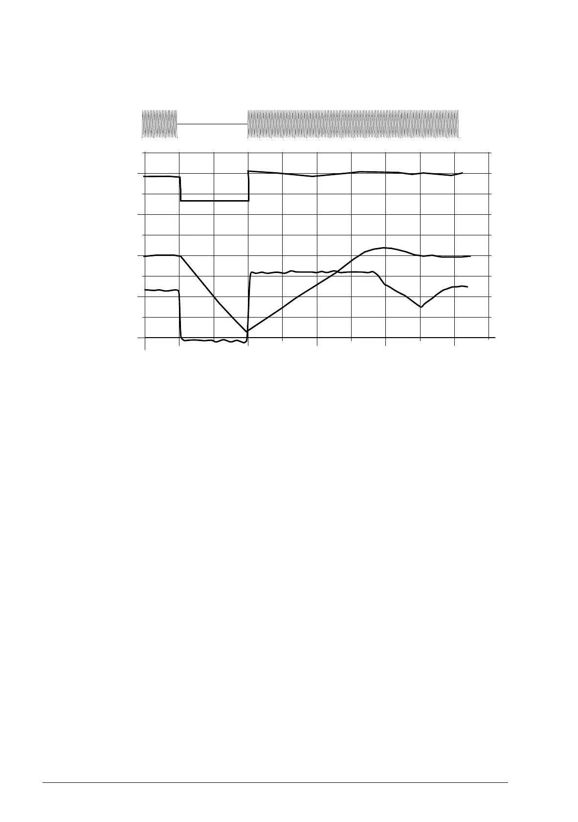
130
260
390
520
1.6 4.8 8 11.2 14.4
t (s)
U
DC
f
out
T
M
U
DC
= intermediate circuit voltage of the drive, f
out
= output frequency of the drive,
T
M
= motor torque
Loss of supply voltage at nominal load (f
out
= 40 Hz). The intermediate circuit DC voltage drops to the
minimum limit. The controller keeps the voltage steady as long as the mains is switched off. The drive runs
the motor in generator mode. The motor speed falls but the drive is operational as long as the motor has
enough kinetic energy.
U
mains
20
40
60
80
40
80
120
160
U
DC
(V DC)
f
out
(Hz)
T
M
(Nm)
 Loading...


