70 Program features
Application control
Application macros
See chapter Application macros (page 89).
Process PID control
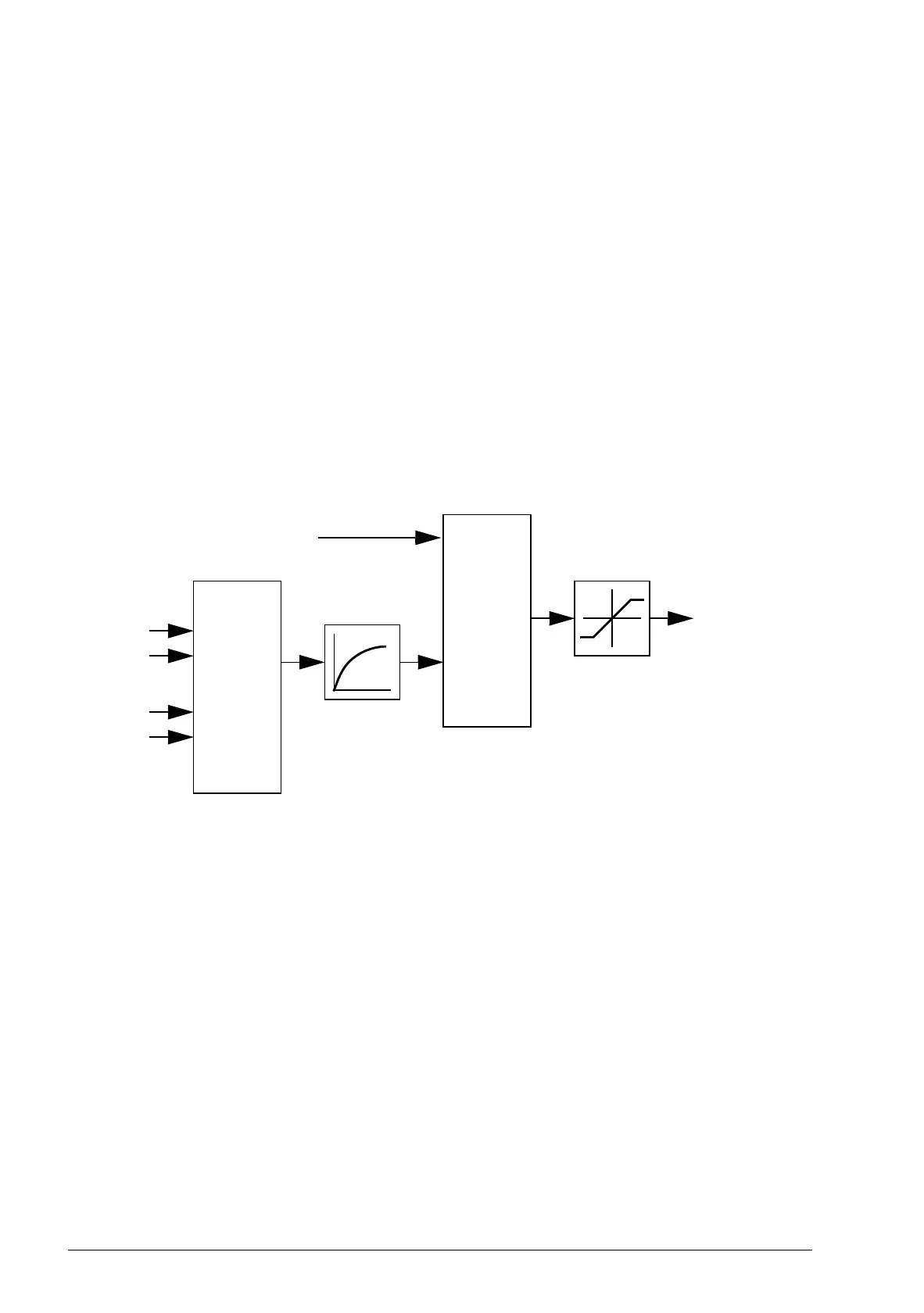
There is a built-in PID controller in the drive. The controller can be used to control
process variables such as pressure, flow or fluid level.
In process PID control, a process reference (setpoint) is connected to the drive
instead of a speed reference. An actual value (process feedback) is also brought
back to the drive. The process PID control adjusts the drive speed in order to keep
the measured process quantity (actual value) at the desired level (setpoint).
The simplified block diagram below illustrates the process PID control.
For a more detailed block diagram, see page 364.
Quick configuration of the process PID controller
1. Select a setpoint source (27.01 PID setpoint sel).
2. Select a feedback source and set its minimum and maximum levels (27.03 PID
fbk1 src, 27.05 PID fbk1 max, 27.06 PID fbk1 min). If a second feedback source is
used, also set parameters 27.02 PID fbk func, 27.04 PID fbk2 src, 27.07 PID fbk2
max and 27.08 PID fbk2 min.
3. Set the gain, integration time, derivation time, and the PID output levels (27.12
PID gain, 27.13 PID integ time, 27.14 PID deriv time, 27.18 PID maximum and
27.19 PID minimum).
4. PID controller output is shown by parameter 04.05 Process PID out. Select it as
the source of, for example, 21.01 Speed ref1 sel or 24.01
Torq ref1 sel.
Process
PID
AI1
Process
actual
values
AI2
• • •
D2D
FBA
Setpoint

 Loading...


