Chapter 2 - Start-Up Instructions
IV F
2 - 8 DCS 600 Operating Instructions
2.2 Scaling intra-unit signals
Make sure that the existing electronics supply voltage has been set on the SDCS-
POW-1 power supply board as well, using the SW1 switch.
If an encoder is being used as the speed feedback device, make sure that the correct
supply voltage has been set on the boards
SDCS-POW-1: ⇒ X3: / X4: / X5: SDCS-IOB-3: ⇒ S4
Switch on the power supply to the electronics section.
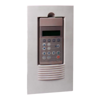
The display of the Control Panel CDP 312 / DRIVES WINDOW may show a
fault or an alarm signal or the seven segment display may indicate an error code
as a sequence of characters and digits.
NOTE: For Software downloading observe the relevant instructions
given on the ”read_me” file of the corresponding Software disc!
Set this only for units with a rated current 25 ... 2000A in case of control board
exchange!
15.02 = 22
After successful saving of the altered data this Parameter 15.02 will be
reset to zero.
Set this only for units with a rated current ≥ 2050A in case of control board
exchange!
42.07 = Rated power converter current
Enter numerical value from rating plate here
42.08 = Rated power converter supply voltage / coding of voltage
measurement (see technical data 5-12)
Enter numerical value from rating plate here
42.09 = 45 degrees Celsius
Temperature monitoring of power section
42.10 = C4 ⇒ Size C4 has been selected
Coding for unit type
42.11 = 1 : Single bridge (2-Q) converter ⇒ on rating plate: DCS 601 xxxx
4 : Double bridge (4-Q) converter⇒ on rating plate: DCS 602 xxxx
Coding for power section (bridge) type
CAUTION! Please don't forget!
Save the altered data of unit type, i.e. Parameters 42.07 ... 42.11:
15.02 = 22
After successful saving of the altered data this Parameter 15.02 will be
reset to zero.
 Loading...
