Chapter 3 - Handling of Control Panel CDP 312
DCS 600 Operating Instructions
IV F
3 - 3
3.3 Panel Functions
The CDP 312 has four different keypad (operation) modes:
• Actual Signal Display Mode (ACT)
• Parameter Mode (PAR)
• Function Mode (FUNC)
• Drive Mode (DRIVE) for further extensions
Actual Signal
Display Mode
ACT
This keypad mode will show, depending on the drive´s history:
• Actual Signals
• Faults
• Fault History Logger
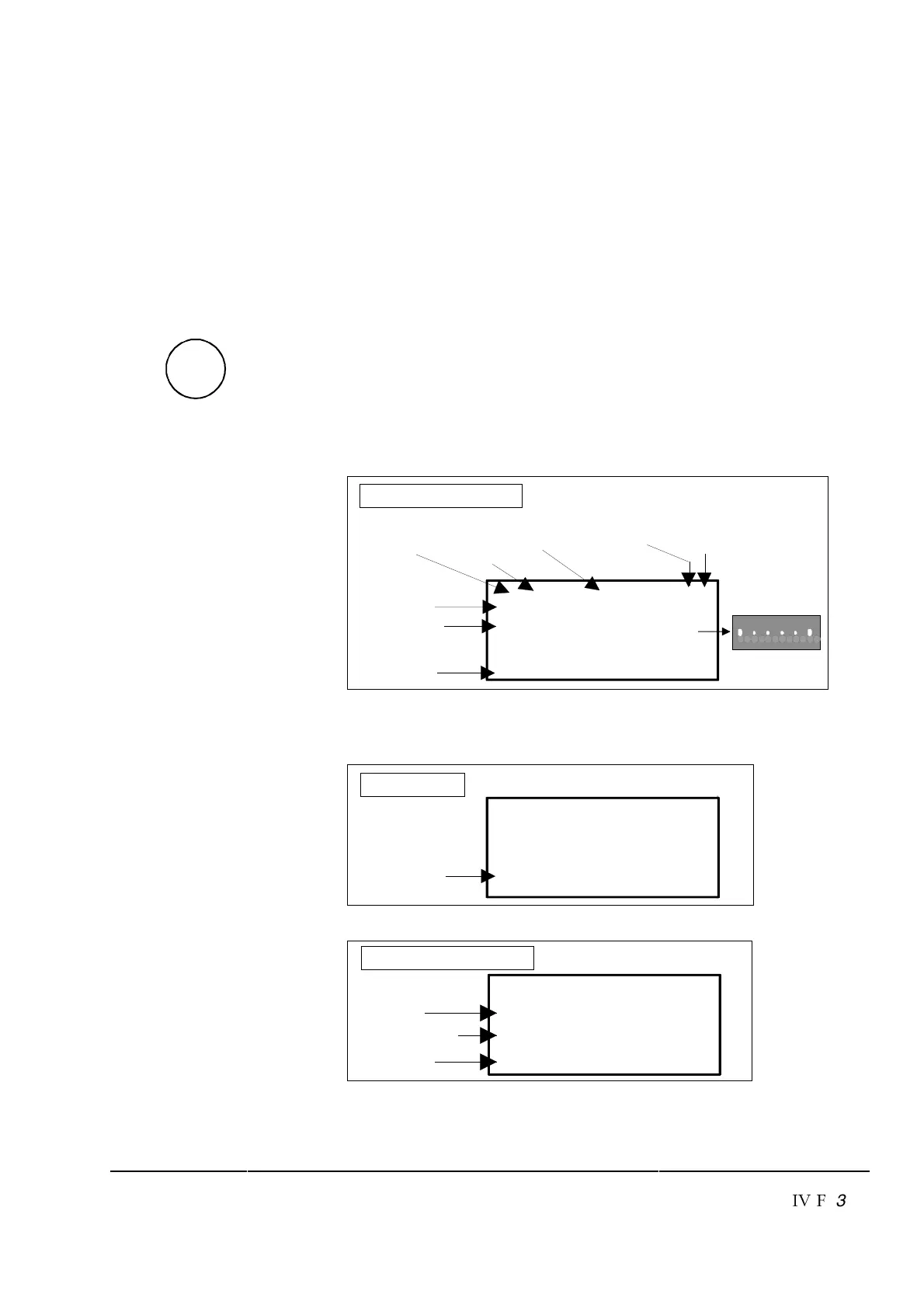
If the ACT-key is pressed immediately after initialization the follow-
ing display is shown. If no panel-key of the CDP 312 is touched
within one minute the Actual Signal Display will appear automati-
cally, except when ”Status Display”
or ”Speed Reference Setting”
is active. (see chapter 3.13 and 3.15)
6\ZW
79>9<=:\ZW
-98@-?<+
6/.:+8/
Run Status
I = RUN
0 = STOP
Speed
reference
rpm
Main contactor
status
0 = Open
I = Closed
Control
Location
L = Local
= Remote
ID-number
of the Drive
Statusrow
Actual Signal
Name, value and unit
I
Cursor shows
the selected row
Actual Signal Display
LED bar (NLMD)
first row also used
for LED bar
050
If a fault occurs in the drive, the Fault Display will appear automati-
cally. This will happen with all other modes as well, except the Drive
Mode is active.
Fault Display
6\ZW
.-=
0+?6>
8Y7-98>
Type of fault or
alarm
To select Fault History Display see chapter 3.8
...
Fault History Display
Fault or alarm name
1 = last fault
2 = second last fault
Total time after
the power up
6\ZW
6+=>0+?6>
897-98>
>37/$2738
Note: For correct display of the LED bar select always 1.26 to the first
row of CDP 312 (default) and select desired signal at 18.01.

 Loading...


