Chapter 4 - Signals and Troubleshooting
DCS 600 Operating Instructions
IV F
4 - 3
4.4 Fault Signals (F)
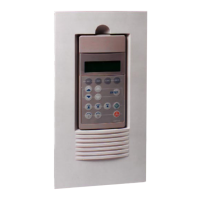
The fault signals will be shown on the seven segment display of
the control board SDCS-CON-2 as codes F . . as well as on the
LCD of the control panel CDP 312 as numbers with text.
Moreover there are fault signals which will only be shown on the
LCD of the control panel.
All fault signals - with the exception of
F 17, F 20 and F 44 - can
be reset (after elimination of the faults).
For resetting (RESET) of fault signals the following steps are
required:
• Switching off the commands ON/OFF and RUN
• Elimination of the faults
• Fault acknowledgement, i.e. resetting (RESET) through input
of the command RESET with APC or in ”LOCAL” mode with
control panel CDP 312/DRIVES WINDOW.
• Depending on the application conditions generate the com-
mands ON/OFF and RUN once more.
The fault signals will result in tripping the drive (installation-de-
pendent).
If a fault occurs, there will be three different possibilities of reaction
(see column ”Remark” in the fault list):
(1)
Fault will switch off the signals energizing the main contactor, the
field contactor and the fan contactor.
(2)
Fault will switch off the signals energizing the main contactor and
the field contactor.
(3)
Fault will switch off the signal energizing the main contactor.
Code
seven
segm.
display
Text on
LCD of control panel
CDP 312
(or DRIVES WINDOW)
Definition /
Action
Status
signal
(FAULT_WORD_
1/2/3)
Remark
F 1
01 AUX UVOLT
Auxiliary voltage fault
The auxiliary voltage (230 V) is too low while
the drive is in operation. If resetting fails,
check internal auxiliary voltages. If fault
persists, change SDCS-CON-2 and/ or
SDCS-POW 1 board (if required).
9.01 bit 0 (1)
F 2 02 OVERCURR
Overcurrent
Check: - Motor, load and armature cabling
for faults or blocking condition;
- Parameter setting of current con-
trol circuit/torque limitation;
- Parameter
[P 42.05]
(overcurrent detection).
- Faulty thyristor
9.01 bit 1
(3)
 Loading...
