Chapter 2 - Start-Up Instructions
DCS 600 Operating Instructions
IV F
2 - 23
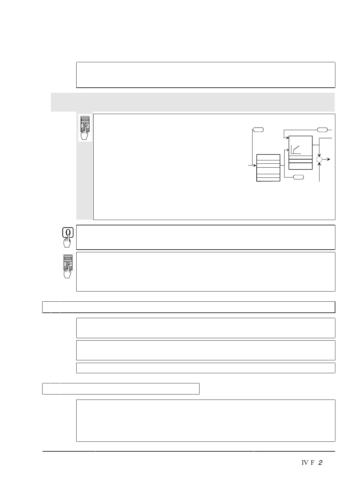
EMF
CONTROLLER
46.03EMF CON KP
46.04
EMF CON KI
V REF 1
3.24
46.12
V REF SLOPE
46.05
EMF CON BLOCK
LEV
46.10
V COR
46.11
V STEP
46.13V LIM P
46.14V LIM N
V ref Modification
V REF 2
3.25
VOLT ACTUAL
3.23
For this purpose, the following parameters at the speed controller must be adapted:
24.03 (KPS) = desired response (behaviour) of controller
24.09 (TIS) = desired response (behaviour) of controller
Only when fine-balancing of the EMF controller is wanted!
(Necessary when work as per section 2.6.3. has been performed)
For assessing control quality, the Fig. entitled "Transient response of controller"
(
⇒ beginning of this chapter) can be used.
41.19 = ? reference armature voltage scaled
to Supply voltage
- If fine-balancing of the EMF controller is wanted,
potentiometers’ settings must be adapted:
17.01 (POT1) approx. 10 % bigger than speed at
field weakening point
17.02 (POT2) approx. 10% smaller than speed at
field weakening point
The following parameters at the EMF controller
must be adapted:
46.03 (EMF_KP) = desired response (behaviour) of controller
46.04 (EMF_KI) = desired response (behaviour) of controller.
Stop the drive and switch OFF power!
15.02 = 0
17.01 = 0
17.02 = 0
99.02 = Rated motor voltage as set in Chapter 2.2
99.05 = Speed at rated motor voltage as set in Chapter 2.2.
2.8 Matching the thyristor power converter unit to the system conditions concerned
- Ramp function generator
- Binary inputs and outputs
- Limit-value messages
- Additional functions
- Link up APC or Fieldbus
2.9 Manual balancing of the controllers
Balancing of the controllers for the armature-circuit current and the field current can be
performed by auto-tuning. If this is not possible for some reason, balancing of these con-
trollers as well as balancing of the controllers for speed and EMF has to be performed
by the skilled technical start-up personnel.
See also the separate Software Description DCS 600, chapter ”Manual Tuning”.

 Loading...


