Planning the electrical installation
28
3ADW000462R0301 DCS880 Hardware Manual e c
Planning the electrical installation
Chapter overview
This chapter contains the instructions that must be followed when selecting the motor, cables,
protections, cable routing and way of operation for the drive system. Always follow local regulations.
This chapter applies to all DCS880 converter modules.
Attention:
If the recommendations given by ABB are not followed, the drive may experience problems not
covered by warranty. See also Technical Guide
.
Options
Line reactors (L1)
For armature and field supply.
When thyristor converters operate, the line voltage is short-circuited during commutation from one
thyristor to the next. This operation causes voltage dips in the mains PCC (point of common
coupling). For the connection of a power converter system to the mains, one of the following
configurations applies:
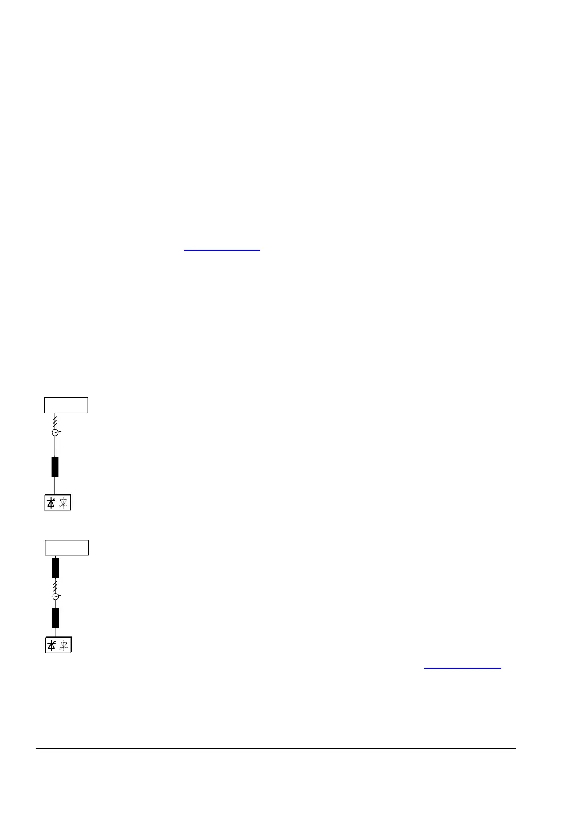
Configuration A
When using a converter, a minimum of impedance is required to ensure proper
performance of the snubber circuit. Use a line reactor to meet this minimum
impedance requirement. The value must therefore not drop below 1 % u
k
(relative
impedance voltage). It should not exceed 10 % u
k
, due to considerable voltage drops
at the converters outputs.
Configuration B
If special requirements have to be met at the PCC (standards like EN 61 800-3, DC
and AC drives at the same line, etc), different criteria must be applied for selecting a
line reactor. These requirements are often defined as a voltage dip in percent of the
nominal supply voltage. The combined impedance of Z
Line
and Z
L1
constitute the total
series impedance of the installation. The ratio between the line impedance and the line
reactor impedance determines the voltage dip at the PCC. In such cases, line chokes
with an impedance around 4 % are often used.
Example calculation with u
kLine
= 1 % and u
kL1
= 4 %:
Voltage dip = Z
Line
/ (Z
Line
+ Z
L1
) = 20 %. Detailed calculations see Technical Guide.
 Loading...