4 Repair
4.4.2. Replacement of complete wrist unit
2653HAC026876-001 Revision: F
© Copyright 2007-2010 ABB. All rights reserved.
Required equipment
Removal, wrist unit
The procedure below details how to remove the complete wrist unit.
Equipment etc. Spare part no. Art. no. Note
Wrist See Spare parts
chapter.
Guide pins M12 x 200 3HAC13056-3 Always use guide pins in
pairs!
Lifting tool, wrist unit 3HAC13605-1
Standard toolkit - The content is defined in
the section Standard
toolkit on page 409.
Other tools and
procedures may be
required. See
references to these
procedures in the step-
by-step instructions
below.
These procedures include
references to the tools
required.
Circuit diagram 3HAC025744-001 See the chapter Circuit
diagram.
Action Note
1. Remove all equipment fitted to the turning disk.
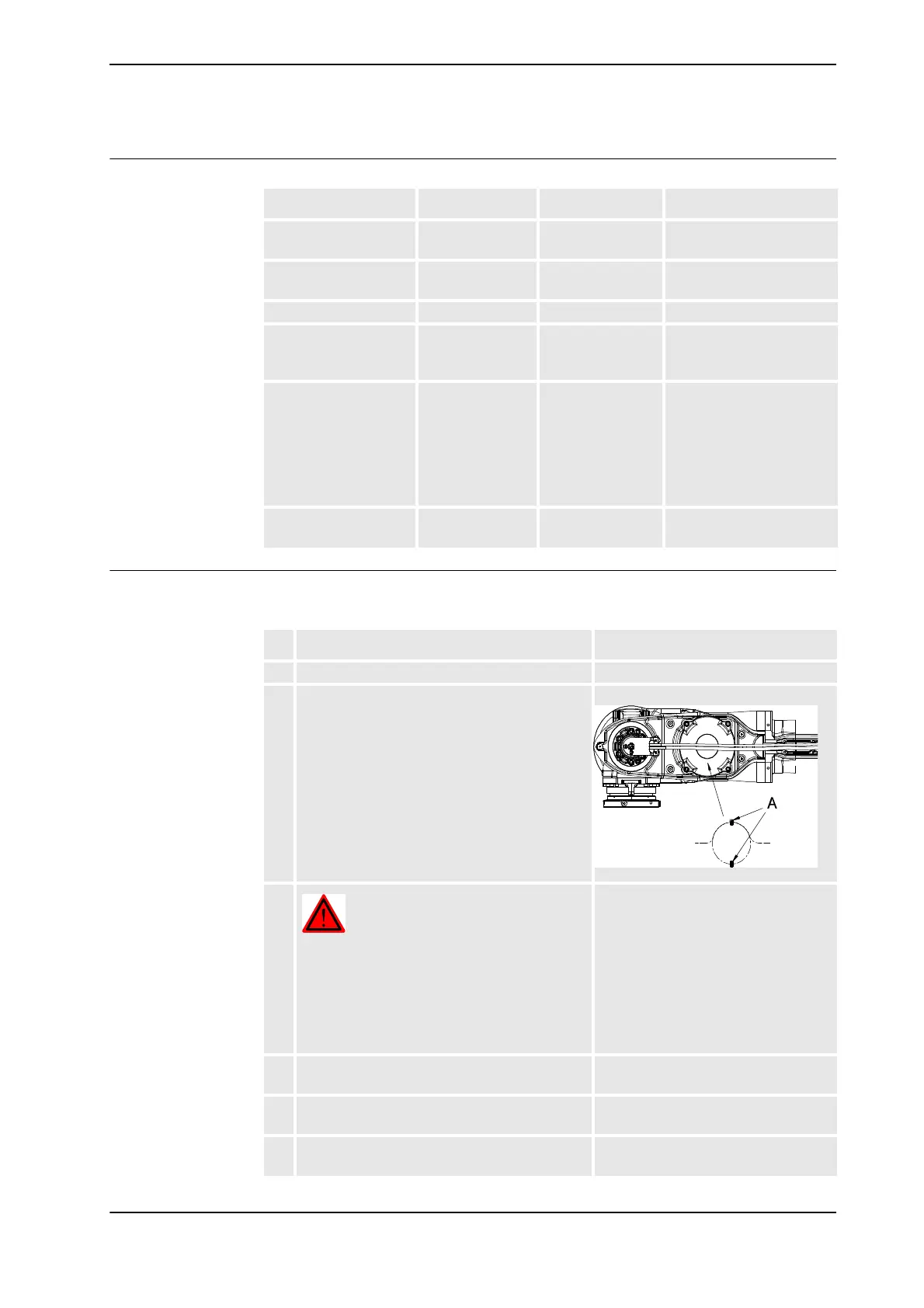
2. Turn axis 4 to a position where the cover, upper
arm tube and wrist unit, faces upwards. Turn
axis 5 to +90°.
xx0200000185
3.
DANGER!
Turn off all electric power, hydraulic and
pneumatic pressure supplies to the robot!
For Foundry Prime robots:
Do not turn off the air pressure to motors and
SMB.
4. Remove the cover, wrist unit. Shown in the figure Location of wrist
unit on page 264.
5. Remove the cover, upper arm tube. Shown in the figure Location of wrist
unit on page 264.
6. Remove the cover of motor, axis 6 and
disconnect all connectors beneath.
Continued
Continues on next page

 Loading...