—
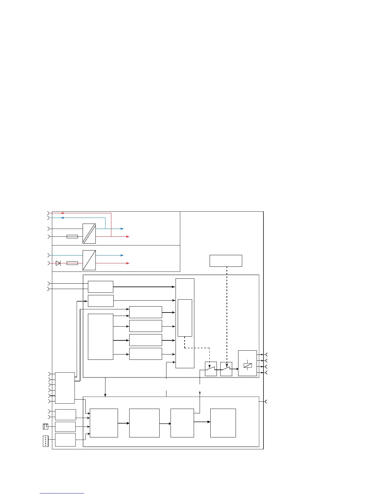
Overview of the major building blocks of UMC100 and the data flow among them.
Building Blocks of UMC100.3
The next diagram shows the major function blocks of the UMC100.3 and the data flow among them.
The upper main block contains the protection-related functions. Signals from different signal sources are evaluated from the trip
unit. Depending on the configuration either a trip or a warning can be created. The motor protection always has priority regarding
control of the relay outputs. In case of a protection trip the relevant contacts are opened and thereafter the motor
is stopped. If the device fails, the watchdog opens the relay outputs automatically for safety reasons. There is no possibility
to bypass this watchdog.
The main inputs for motor protection are the current measurement and the thermistor sensor. The current measurement
provides information about the actual motor current in the three phases. An advanced motor model uses the current
information and calculates the corresponding motor temperature. At a certain level it will trigger an overload trip.
The thermistor input measures the PTC resistance. Based on the resistance the cold and hot state of the motor can be
distinguished. Also short-circuit or wire break conditions can be detected.
The lower main block contains the control-related functions. Incoming commands from the panel, the digital inputs or the
fieldbus are ranked from the control place selection block according to the user settings and then forwarded to the active starter
function.
The starter function block controls the relay outputs depending on its input signals and the actual state. Additionally monitoring
signals are prepared for the LCD display, the UMC100.3 signalling LEDs and the fieldbus monitoring and diagnosis telegrams.
All these blocks run in the so-called logic engine. It is possible to change the application which is running there but usually the pre-
defined applications will be sufficient. Further information about the creation of custom applications can be found in the Custom
Application Editor manual.
 Loading...