—
7 Using Expansion Modules
In this chapter you learn how to use the UMC expansion modules. Expansion modules allow you to increase the number of inputs
and outputs. For information on how to connect the IO modules to the UMC read the ‘Installation’ chapter. The IO module's
status messages are described in the chapter ' Error Handling, Maintenance and Service'.
Using a Digital IO Module (DX111-FBP.0/122-FBP.0)
To activate a digital IO module set parameter DX1xx-FBP.0 Enabled to On. If a module is enabled the UMC monitors the presence of
the module and creates by default a fault in the event that the module is missing (-> parameter 'Missing Module Reaction').
Using the Digital Inputs
By default all eight digital inputs are available in the fieldbus monitoring telegram. They can thus be directly used in the
PLC/DCS application.
For inputs 1DI0 to 2DI5 the following additional options exist:
• Each input can separately trigger a fault or warning with a unique error code and error message that is shown on the
UMC's LCD panel.
• A fault can be automatically cleared when the cause of the fault is rectified.
• Each input can optionally be delayed. (see parameter DX1xx-FBP.0 DI delay for details)
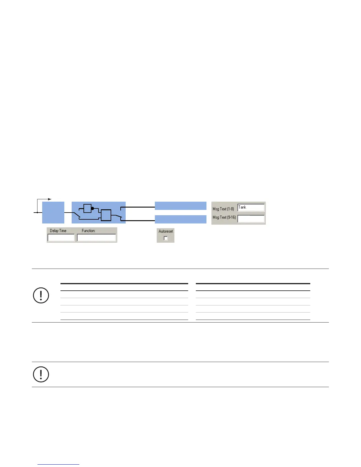
The following figure shows the internal data flow of the inputs 1DI0 - 2DI5.
Functionality of the six digital inputs 1DI0 - 2DI5 of the DX111-FBP.0 and DX122-FBP.0 modules
Internally the digital inputs of the DX1xx module are connected to a function block called 'AuxFaultWarn' with six
inputs called Aux1 to Aux6. The following table shows which IO module input relates to which parameter set:
DX1xx input Parameters DX1xx Input Parameters
1DI0 Aux. Inp. 1 1DI4 Aux. Inp. 5
1DI1 Aux. Inp. 2 2DI5 Aux. Inp. 6
1DI2 Aux. Inp. 3 - -
1DI3 Aux. Inp. 4 - -
Using the Relay Outputs
The 4 relay outputs are connected to the fieldbus command telegram and can be freely used by the control system.
By default they are not used by the UMC in any way. See the fieldbus command telegram for the relevant bit positions.
The inputs and outputs of the modules DX122-FBP.0 and DX111-FBP.0 can be freely used in the Custom Application
Editor.
Consult the editor's manual if you plan to use the inputs or outputs directly in the UMC.
99