Voltage and Power Protection Functions
This section describes the voltage based motor protection functions. The UMC100.3 together with the voltage module VI150/VI155
continuously measures the motor supply voltage (line to line), the motor current and the phase angle between the current and vol-
tage. The power and energy consumption is calculated out of these values and used for various protection and monitoring func-
tions. The different process values can be reported to the fieldbus and displayed on the LCD panel.
The following functions are described in this section:
• Overvoltage, Undervoltage
• Phase loss
• Voltage imbalance
• Total harmonic distortion
• Overload, Underload
• Power factor
• Voltage Dip reaction
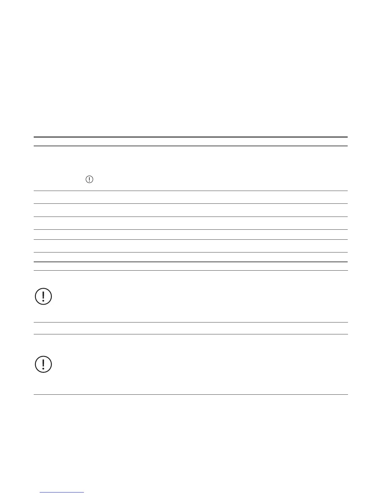
The following process data are available:
Process Value Explanation Data range
Powerfactor (cosphi)
The power factor is defined as the ratio of the real power flowing to
the load to the apparent power and is a non dimensional number
(also expressed as a percentage).
The cos phi only considers the fundamental frequency.
In this manual both terms are used and refer to the fundamental
frequency only!
U
, U
, U
U
LN
Phase to phase (line to line) voltages (three-phase mode)
Phase to neutral (single-phase mode)
e
Active power
Active power is the capacity of the motor for performing work in a
particular time
The actual unit depends on the selected scaling factor.
Apparent power The apparent power is the vector sum of real and reactive power.
The actual unit depends on the selected scaling factor.
Voltage Imbalance An imbalance between the supply voltages in the network.
Total harmonic
distortion (THD)
Harmonic distortion of the mains.
Energy Consumed energy. kWh
In section 2 -> Connecting the VI15x Voltage Module you will find information on how to mount and connect the
voltage module.
All process values generated from the voltage module can be used in the Custom Application Editor. Consult the
editor's manual for more information.
The digital output of the voltage module DO0 can be freely used in the function block editor.
By default it is connected to the command telegram and can be controlled from a PLC.
Before using the voltage module set the following parameters:
• Nominal line to line voltage (three-phase mode)
• Nominal to neutral voltage (single-phase mode)
• Nominal power factor (cos phi)
• VI15x enabled.
If the module is enabled the UMC monitors the presence of the module and creates by default
a fault in the event that the module is missing (-> parameter 'Missing Module Reaction').
49
 Loading...