T
t[s]
T1
T2
T4
0
20
40
60
80
100
120
0 200 400 600 800 1000 1200 1400 1600
T3
θ
R
T5
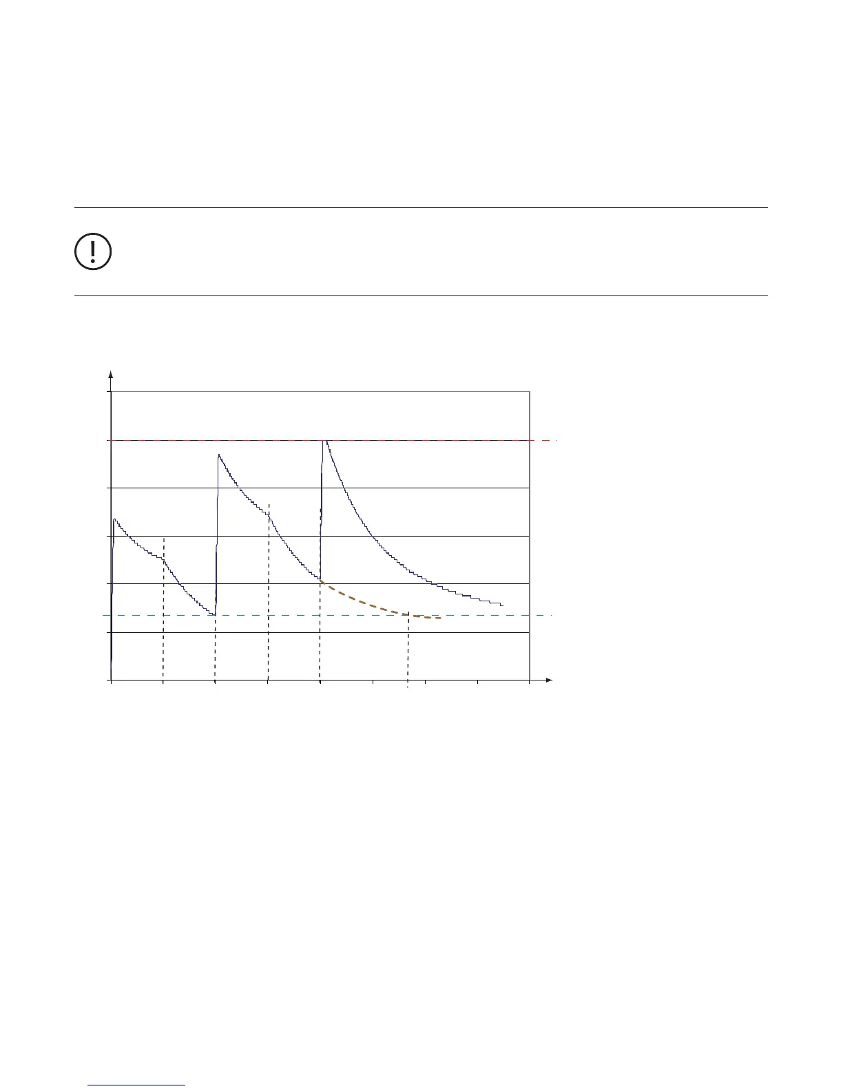
Cyclic motor operation modes
Some applications require periodic start/operation/stop cycles. Setting up such applications requires care when selecting the
cooling down times or defining the shortest possible start period. In the next diagram three successive start cycles are displayed.
-
set to 200 s). After the cooling time is over the next start takes place at T2. During this cycle the motor also cools down for 200 s
For cyclic operation modes it is important to keep the cycles long enough to allow the motor to cool down suffici-
ently. For cyclic start patterns it is better to select the cooling mode option "Restart Level" which allows a restart
based on the thermal load level. In the case shown below the third start would then be allowed at the earliest at T5
for the given q
R
.
—
Trend of the calculated motor temperature after several starts.
The motor trips after the third start because the motor was started too frequently in the given time
Relevant Parameters:
• Trip Class
• Set Current I
e1
and optionally I
e2
• Current Factor
• Cooling Mode
• Cooling Time
• Restart Level
• Thermal load Pre-Warning level
• Fault autoreset
q
T
: Thermal load of the motor
q
R
: Configured Restart Level
T
x
: Switching time
t: Time
40
 Loading...