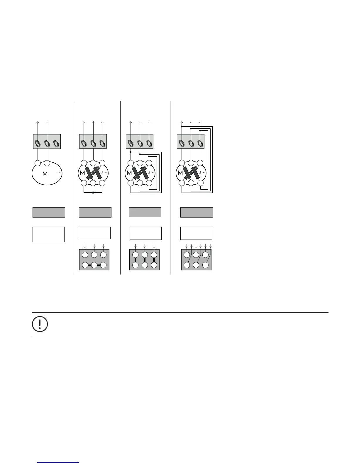
Motor Wiring
The following diagram shows different methods of connecting a motor. For a reliable motor protection it is essential to set
the correct nominal current I
e
.
Note:
For inner-delta wiring the parameter Current Factor
motors to reduce the current transformer size.
Related Parameters:
• Nominal current Ie1
• Current factor
U2
W2
V2
V1 W1U1
UMC
U2W2 V2
V1 W1U1
400 V / 690 V
W2
U1
U2
V1 W1
V2
UMC
U2W2 V2
V1 W1U1
400 V / 690 V
V1 W1U1
W2
U2 V2
UMC
U2W2 V2
V1 W1U1
400 V / 690 V
Star
Power line: 690 V
Delta
Power line: 400 V
3 wiring
Power line: 400 V
Example for motor:
Motor rating plate
Example for motor:
Motor rating plate
Example for motor:
Motor rating plate
4.9 A / 2.8 A
4.9 A / 2.8 A4.9 A / 2.8 A
Parameter
Set Current = 2.80
Current factor = 100
Parameter
Set current = 4.90
Current factor = 100
Parameter
Set current = 4.9
Current factor = 173
Terminal box
Terminal box
Terminal box
I
P
= 2.8 A / I
SC
= 2.8 AI
P
= 4.9 A / I
SC
= 4.9 AI
P
= 4.9 A / I
SC
= Ip/√3=2.80
I
SC
=
I
P
I
SC
=
I
P
I
SC
=
I
P
* 0.577
I
P
I
P
I
P
2CDC 342 020 F0209
I
P
= Actual current / phase
I
SC
= Set current
UMC
LN
230 V
Single phase
Power line
Example for motor:
Motor rating plate
2.5 A
Parameter
Set Current = 2.50
Current factor = 100
I
e
= 2.5 A
NL
L1 L2 L3
L1 L2 L3 L1 L2 L3
1
It is optional to feed N through the UMC if ground fault detection is disabled.
24
 Loading...