—
6 Configuring the Communication Interfaces
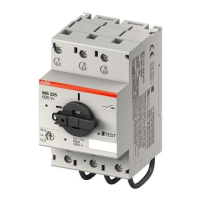
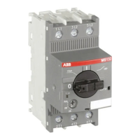
The UMC can be integrated into different fieldbus and Ethernet networks with the help of a communication interface. Communica-
tion interfaces exist for PROFIBUS DP, PROFINET IO, DeviceNet, Modbus RTU, ModbusTCP and EtherNet/IP™. Since the communi-
cation networks and the various communication master configuration tools are very different no common integration procedure
can be described here. In general the following generic steps are usually necessary:
1. Make the UMC known to the engineering tool e.g. by importing the device description file (GSD, GSDML, EDS)
2. Create a network and insert nodes like the UMC as required
3. Set the UMC parameters according to your needs (if parameterisation from within the system is required)
4. Make the I/O signals available in your programming tool (e.g. a IEC61131 based tool)
To use the UMC in a fieldbus network the following parameters should be considered.
Setting the Bus Address
The bus address can be adjusted with the UMC LCD panel. The UMC allows an address to be set between 000 and 255. But there
are different limitations depending on the fieldbus in use. Setting the address to 255 means that the UMC will take over the ad-
dress from a connected communication interface.
• PROFIBUS: 2 ...125
• DeviceNet: 2 ... 64
• Modbus: 2 ... 125.
Ensure that the chosen bus address is not used twice. If an address is used twice the whole bus line might go out
of operation.
Related Parameter: Bus Address
Specific Communication Settings for Modbus RTU and DeviceNet
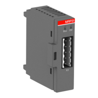
For the Ethernet modules PNQ22-FBP.0 for PROFINET and MTQ22-FBP.0 for ModbusTCP also a bus address has to be set for each
configured port. But this address is only for the "Address Check" feature described in the section below to identify if the right
UMC100.3 is connected.
The EtherNet/IP™ module EIU32.0 uses the last octet of the IP address for identification, and the connected UMC100.3 needs to
be set to the same address. Generally Ethernet devices use TCP/IP address for node addressing.
Related Parameter:
• Address Check
• DeviceNet baudrate
• MODBUS baudrate
• MODBUS frame
• MODBUS bus timeout
Specific Communication Settings for Ethernet
For single Ethernet interfaces like EtherNet/IP™ EIU32.0 there are additional settings
• IP setting mode DHCP, Basic, User defined
• IP address octet 1, 2, 3, 4
• Subnet mask octet 1, 2, 3, 4
• Gateway octet 1, 2, 3, 4
• Enable webserver On, Off
95
 Loading...