SM500F
Field mountable paperless recorder 2 Installation
IM/SM500F Rev. Z 17
2.3.2 Connections
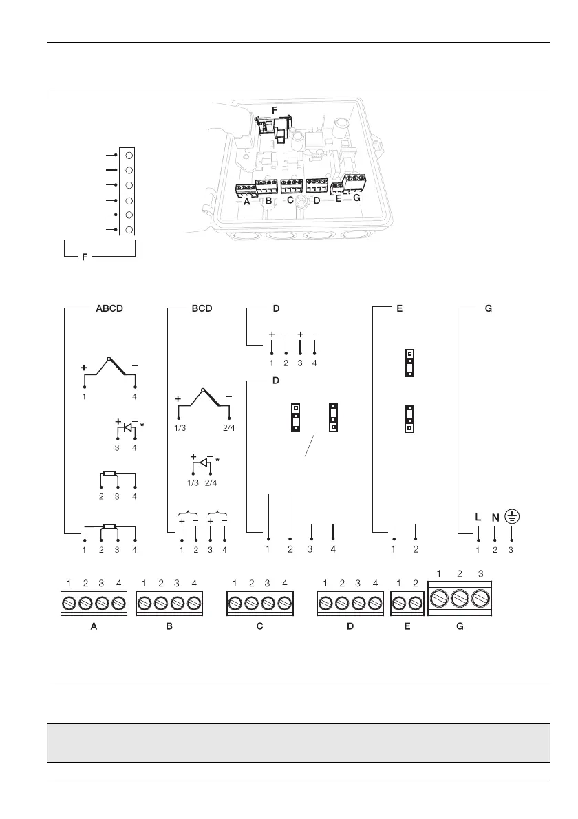
Fig. 2.8 Electrical Connections
Note. Power supply terminal screws must be tightened to a torque of 0.8 Nm (7 lbf.in). All other terminal
screws must be tightened to a torque of 0.5 Nm (4.5 lbf.in).
Ethernet/Modbus and
Digital Input
Rx/Tx +
Rx/Tx –
Gnd
Dig IP/1
Dig IP/2
Dig Com
Single Input Dual Input 24 V Tx PSu Relay Power
Supply
THC/mV/V
Digital Input
Current
R/RTD 3
RTD 4
Current
THC/mV/V
Digital Input
I/P 1 I/P 2
Dual Relay
Relay 1
Relay 2
Relay 1
Relay 2
NO
NC
CNO/NC
CNO/NC
LK1 LK2
Relay
NO
NC
LK1
CNO/NC
10 to 36 V DC or
100 to 240 V AC
* In the powered-down condition the current input is open circuit. In order to maintain a current loop when
the recorder is powered down, fit a zener diode (BZX79 – B/C2V4) to the input as shown.

 Loading...