SM500F
Field mountable paperless recorder 2 Installation
IM/SM500F Rev. Z 21
2.7 Transmitter Power Supply Module
One transmitter power supply module can be fitted in position D to provide a nominal 24V supply capable
of driving two, 2-wire transmitters.
2.8 Relays
One relay is provided as standard (position E). An additional relay module can be fitted in position D to
provide two additional relays.
The maximum individual relay current is 5A.
Relay contacts are fitted with arc suppression components as standard.
Set the polarity using the relay links provided on the recorder's motherboard (for the standard relay) and the
relay module board (for the optional additional relays) – see Fig. 2.8, page 17.
2.9 Modbus/Digital Input
A Modbus/digital input module can be fitted in position F to provide a 2-wire isolated RS485 interface and
2 digital inputs.
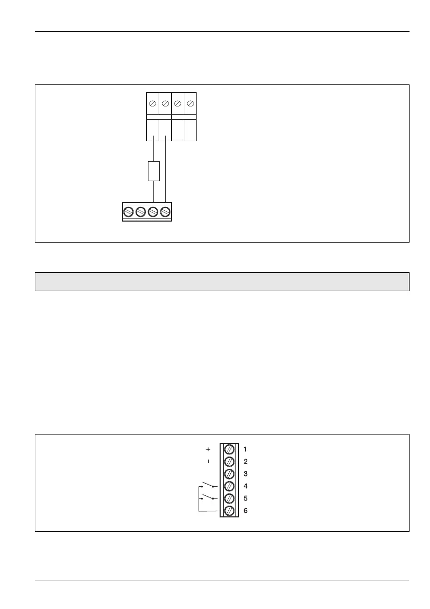
Fig. 2.12 Transmitter Power Supply Module
Note. Analog input terminal screws must be tightened to a torque of 0.5 Nm (4.5 lbf.in).
Fig. 2.13 Modbus/Digital Input Module
2-wire Transmitter Power Supply
(24V DC, 22mA max.)
Analog Input
Rx/Tx +
Rx/Tx –
GND
Dig In 1
Dig In 2
Common
 Loading...