30 TTF300 FIELD-MOUNT TEMPERATURE TRANSMITTER | OI/TTF300-EN REV. I
… 8 Electrical connections
Protection of the transmitter from damage
caused by highly energetic electrical
interferences
The transmitter has no switch-off elements. Therefore,
overcurrent protective devices, lightning protection, or voltage
disconnection options must be provided at the plant.
For the shielding and grounding of the device and the
connection cable, observe Recommended shielding / grounding
on page 31.
Temperature transmitter damage!
Overvoltage, overcurrent and high-frequency interference
signals on the supply connection as well as sensor connection
side of the device can damage the temperature transmitter.
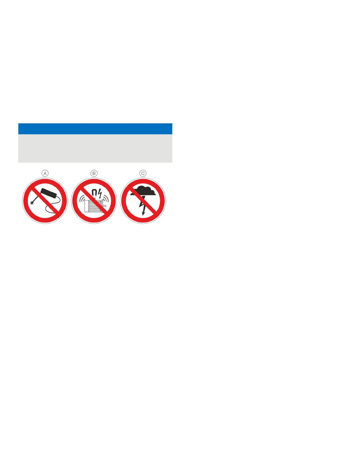
Do not weld
No high-frequency interference signals / switching operations of large
consumers
No overvoltage due to lightning
Figure 20: Warning signs
Overcurrent and overvoltage can occur through for example
welding operations, switching operations of large electric
consumers, or lightning in the vicinity of the transmitter, sensor,
as well as connector cables.
Temperature transmitters are sensitive devices on the sensor
side as well.Long connector cables to the sensor can encourage
damaging interference.This can already happen if temperature
sensors are connected to the transmitter during installation, but
are not yet integrated into the system (no connection to the
supply isolator / DCS)!
Suitable protective measures
The following items should be observed to protect the
transmitter from sensor-side damage:
• In the vicinity of the transmitter, sensor and sensor
connector cable in case of a connected sensor, high-
energy overvoltage, overcurrent and high-frequency
interference signals due to welding operations, lightning,
circuit breakers or large consumers of electricity among
others should be absolutely avoided.
• The connection cable of the sensor on the transmitter
should be disconnected when performing welding work in
the vicinity of the installed transmitter, sensor, as well as
supply lines from the sensor to the transmitter.
• This correspondingly also applies to the supply side, if
there is a connection there.
Conductor material
Power supply cable
Maximum cable outer diameter:
12 mm (0.47 in)
Maximum wire cross section:
2.5 mm
2
(AWG 16)
Cable glands
The cable diameter must be appropriate for the cable gland used
so that IP rating IP 66 /IP 67 or NEMA 4X can be maintained. This
must be checked during installation.
For delivery without cable gland (thread M20 × 1.5 or NPT ½ in),
the following points must be observed:
• Use cable glands in accordance with version M20 × 1.5 or
NPT ½ in.
• Observe information in the data sheet for the cable gland
used.
• Check the working temperature for the cable gland used.
• Check the IP rating IP 66 / IP 67 or NEMA 4X of the cable
gland used.
• Check the Ex relevant specifications for the cable gland
used in accordance with the manufacturer data sheet or
the Ex declaration.
• The cable gland used must be approved for the cable
diameter (IP rating).
• Observe tightening torque in accordance with
information in data sheet / operating instructions for the
cable gland used.

 Loading...


