TTF300 FIELD-MOUNT TEMPERATURE TRANSMITTER | OI/TTF300-EN REV. I 39
Output – FOUNDATION Fieldbus®
Note
The FOUNDATION Fieldbus® protocol is an unsecured protocol,
as such the intended application should be assessed to ensure
that these protocols are suitable before implementation.
Output signal
• FOUNDATION Fieldbus H1 (IEC 611582-2)
• Baud rate 31.25 kBit/s, ITK 5.x
• FISCO compliant (IEC 60079-27)
• Device ID:000320001F...
Error current signal
• FDE (Fault Disconnection Electronic)
Block structure*
• Resource Block
• Transducer Block 1 – Temperature
• Transducer Block 2 – HMI (LCD indicator)
• Transducer Block 3 – enhanced diagnosis
• Analog Input 1 – PRIMARY_VALUE_1 (Sensor 1)
• Analog Input 2 – PRIMARY_VALUE_2 (Sensor 2)
• Analog Input 3 – PRIMARY_VALUE_3 (Calculated Value**)
• Analog Input 4 – SECONDARY_VALUE (reference junction
temperature)
• Analog Output – optional HMI display
(Transducer Block 2)
• Discrete Input 1 – extended diagnosis 1
(Transducer Block 3)
• Discrete Input 2 – extended diagnosis 2
(Transducer Block 3)
• PID – PID controller
LAS (Link Active Scheduler) link master functionality
* For the block description, block index, execution times, and
block class, refer to the interface description
** Sensor 1, Sensor 2 or difference or mean
For detailed information, see the COM/TTX300/FF
FOUNDATION Fieldbus® interface description.
Power supply
Two-wire technology, polarity safe; power supply lines = signal
lines
Note
Following calculations apply for standard applications. This
should be taken into consideration when working with a higher
maximum current.
Power supply – HART®
Supply voltage
Non-Ex application:
U
S
= 11 to 42 V DC
Ex applications:
U
S
= 11 to 30 V DC
Maximum permissible residual ripple for supply voltage
During communication this is in accordance with the HART FSK
‘Physical Layer’ specification.
Undervoltage detection on the transmitter
If the terminal voltage on the transmitter down-scales a value of
10 V, this may lead to an output current of I
a
≤ 3.6 mA.
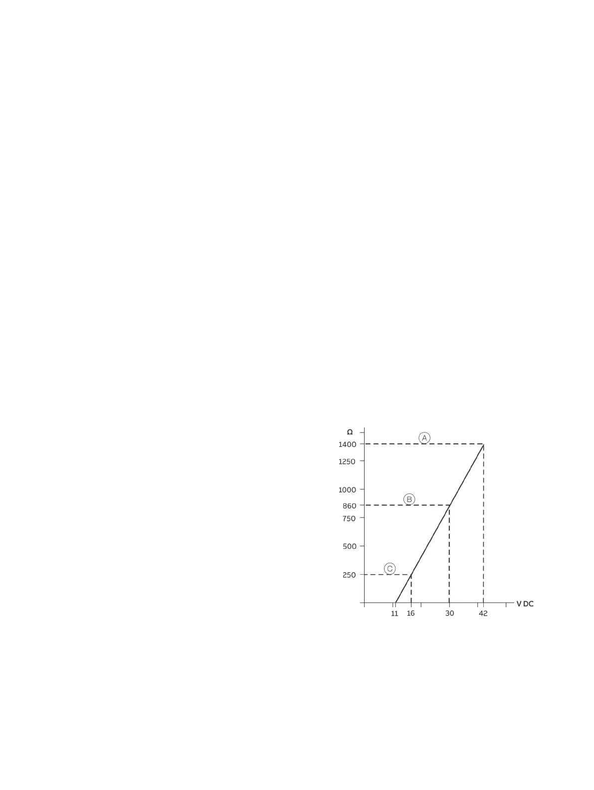
Maximum load
R
B
= (supply voltage−11 V) / 0.022 A
TTF300
TTF300 in Ex-applications
HART communication resistance
Figure 29: Maximum load depending on supply voltage
Maximum power consumption
P = U
s
x 0.022 A
E.G. U
s
= 24 V P
max
= 0.528 W

 Loading...


